Gizmo schematics, key to troubleshooting and updating
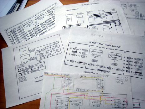
Something I was very pleased to find on the ever more likely future Gizmo is extensive documentation on its DC and AC wiring. In that fairly random sampling above you can see a conceptual diagram of major systems, detailed panel flow charts and layouts, and — most impressive, really — a hand drawn schematic made when a second 30 amp shore power input was added sometime in the boat’s relatively short history. There’s much more, including cable by cable wire chase assignments and voltage drop calculations, and most of those cables are physically labeled. Thank goodness, as this is the aspect of the yacht I’m the dumbest about. I won’t feel like Gizmo’s truly able master until I better understand her electrical systems, and what to do when troubles arise. Plus, despite being thoughtfully and carefully put together in 2000, there’s so much useful electrical and electronic updating that could be done in 2009…
Now, if I should own this boat in a couple of weeks, I’m not going to tear up its systems right away. That would be really dumb. But eventual possible improvements include: networked and redundant navigation systems; better engine and electrical monitoring; networked WiFi and/or cellular Internet connections; solar charging system, LED lighting, and more efficient heat/air (not invented yet); better sensors of all sorts, and a NMEA 2000 network to share them; AIS Class B transponder to be sure; etc. etc. Marine electronics have evolved a lot since 2000!
My good luck — besides being able to get the boat itself — is that in many cases I won’t have to make long term gear decisions. Instead I’ll borrow systems, install them, compare them, write about them, return them, and look for the next new, new thing. But even if I was just doing ‘normal’ updates, this boat’s fairly good electrical documentation would help a lot. I hope to keep the schematics and wire labeling up to date, maybe even improve on them, because I’m pretty sure that there’s a special place in heaven for boat owners and installers who leave good information for the next owner or installer 😉 What’s also going to help is this particular boat’s accessible wire chases and the hunkiest mast I’ve ever seen on a power boat this size. That’s me standing on the ends of the port side spreaders (look here to see the whole mast), which didn’t even twitch under the load. Did you say “antenna farm”?





Lucky you! I’m still reverse-engineering massive unlabled cable harnesses, chasing beeps with signal tracers, labeling things, and pulling out many pounds of abandoned runs left over from ancient refits (if they cannot be repurposed). Maddening, really. If I were buying now, current documentation and accessibility would be very high on the list of criteria. My boat was very well done by the PO/PPO, but there is only one snapshot of the systems and it is far from current.
-Steve
Amazing! You are lucky!
As a marine tech/installer I encounter many expensive production boats right out of the factory with at most a drawing of the breaker panel and a block diagram.Good luck tracing anything.
(I will not name names but most are guilty).
One of the best things about building my own sailboat was getting to wire it completely from the get go.I know every wire is sized correctly, no hidden splices, lots of breakers, etc, etc.
Oh yeah…a full set of drawings too of course!
After spending most of the day yesterday trying to decipher the French used in my customer’s Lagoon 47, I’m looking forward to following in Steve’s path and developing schematics “on the fly” using OmniGraffle and a Wacom tablet. Maybe years from now someone will come across a boat I’ve worked on and appreciate the extra effort like you have.
Echoing what Catamaran Pete said, there are far to many production boats with woefully inadequate systems documentation. Both NMEA and ABYC cite proper labeling as a requirement for an approved installation, but rarely do we get “as-built” drawings for a vessel. Things change quite a bit from the engineer’s desk to the shop floor.
How does the execution and installation of the systems on “Future Gizmo” look? By the book, neat and clean?
Ben, would you be willing to tell us a little bit about how you plan to maintain the documentation? Specifically do you plan on keeping electronic (e.g. done on the computer and stored in files) or paper (pen and pencil) documents?
If you are using the computer, what software do you use for this purpose?
Thank you.
For JonnyBoats: I have been using SmartDraw, a business charting software, for several years in my electrical business. It is not expensive, the tech support is free and friendly, and the learning curve is steep but short. You can be putting out pretty decent wiring diagrams after about four hours of tutorial. Here is the website: http://www.smartdraw.com/ If you buy before 4/6/09 you will save $100 on the single license version.
No affiliation other than a very happy user.
CharlieJ
I am the original owner of my sailboat which I got almost 23 years ago. It came with a wiring diagram of the panel. Since that time I have upgraded electrics and added oodles of stuff. A few years ago when I redid the mains, monitor, batts, switches etc. I pulled out left behind wires and embarked on a series of wiring diagrams which are not technically correct electrical schematics, but a cross between a schematic and graphic representation of each system showing the wires, their color and their gauge, busses etc. and I have labeled a fair amount of the wiring as well. In addition, and to aid in this task, since I CAD from home and from memory I have taken digital photos so I can refer to and have another form of documentation. I have also printed the OEM equipment manuals and am assembling a ship’s manual. It’s a labor or love.
Even with the wiring “cleaned up” considerably there’s still a lot of wires and just looking at them doesn’t help. For example behind my panel is a 20 position buss for neg returns. But looking at those wires you can’t tell which fixture/item the wires come from, so I do graphic diagrams. after I identify them. I have 8 different diagrams so far.
I don’t want to rain on the parade, but I suggest you take a few random wires within the boat, and use them to validate the documentation.
Sometimes, hopefully not here, the documentation is pretty, but doesn’t actually document the system. Sometimes the documentation is done by one guy, but doesn’t reflect the reality of what the electrician actually did.
What Russ said. Also, sometimes the documentation is block-diagram level, and not quite “real.” In the case of my boat, there is a huge disconnect between the diagrams and reality, even where the original cabling is concerned.
There are really three orthogonal views needed: system-oriented block diagram, real details, and routing. I’m on my boat at the moment, wiring the new Wema tank sensors to a trio of Maretron TLA100 boxes… and it is so difficult to find the old stuff that in two cases I’m just running new stuff. This creates even more orphan runs, completely counter to my design philosophy, but all I see on the “schematic” is a terminal strip with AFT, STBD, and PORT fuel labels.
As I find interconnects (or add new ones) I database them. It’s a little arcane, but I set up a relational system in FileMaker, with linked databases for objects and connections. It isn’t the kind of thing you can stare at for an “aha!” understanding of a system, but it gives me a place to hang PDFs, drawings, comments, serial numbers, vendor names, and a traversable mesh network of the whole mess.
I see why people sometimes just start over!
Cheers,
Steve
Trust me, Russ, I know the documentation may not reflect reality, but at least it’s a start.
I don’t know what routine I’ll develop to document systems. I’ll probably try Visio first, as I own a copy. I recognize, as Steve points out, that there are multiple levels that should be captured, from the conceptual to the actual cable runs. Digital photos will be useful.
My biggest concern, really, is not getting around to it. That’s the Catch 22. Once you’ve trouble shot a problem or figured out how to install an upgrade successfully — no doubt taking three times longer then expected — that’s the moment you should update the documentation. But it’s also a moment when you really don’t need to!
Once you’ve trouble shot a problem or figured out how to install an upgrade successfully — no doubt taking three times longer then expected — that’s the moment you should update the documentation.
As you say, this doesn’t usually work. A better approach is to document as you go along. There is no ‘final’ version, just a ‘last’ version. Every version could end up being the last, the one where you left off (finished or not) to work on another problem. Even if you intend to come back soon and continue work, it will probably only be after you have forgotten important details.
Be it Visio (which I use) or some other tool, I struggle on the layout of the diagram between the physical layout, the logical layout, and creating critical clarity between grounds/bonding wiring … for me that is a third diagram altogether which I used to troubleshoot the incorrect installation of my link 20.
Each time I have an upgrade and discover more about the pre-existing wiring in my boat, I find it difficult to upgrade existing visio diagrams and then either start with new diagrams … or put off until later when I have time to shift the diagram around to make space for new information.
Look at a fuse on some diagrams … and you can know exactly where it is and have an immediate sense for the length of the wires even, but not so on other diagrams and have no idea where the fuse is.
There are little green tags all over my engineering spaces as I discover the purposes of unmarked wires, just waiting to be transferred onto new visio diagrams.
… but that dosn’t happen as … I do like to sail sometimes.
Somehow I think I anyone using visio or similiar tools are just destined to have little benefit over hand written diagrams.
The ideal software tool would allow you to enter information on each wire, one at a time … whenever, without having to draw it nice and pretty onto a diagram. A visual GUI would be helpful of course … just make it so you have a bunch of components, some conduits, and you just lay the wire from component A, thru each conduit, and to component B … then answer some questions about the gauge of the wire, color, markings on each end, and the marking the component has where the wire connects (e.g +12, nmea in, etc.)
Personally … I prefer paper output, but I wouldn’t entirely mind if I could only access the information from my laptop and could select a filter on what I want to see (a component, conduit, or relationship (e.g. all the ground wires), and then the software draws a representation on the fly to show me what I need as either:
(1) A physical representation. (e.g. how the wire is routed thru the boat)
(2) A logical representation focused on what I filtered for (grounding & bonding, +12 power from a specific breaker on out, network xyx, my boatspeed sensor, etc.)
Does this exist ?
Dan,
I remember that 15 years ago my company had a big consulting gig creating the database behind a graphical GIS developed by a then well-known manufacturer of large graphic display terminals. They figured they could deliver a visio-like approach to a utility company. Of course it didn’t work.
My lesson learned is that over time the database is more important (and easier to keep right) than the diagram.
So my vote is for a block diagram backed up by a database. The professional solution would be able to go back and forth between the two. I fear that we mere mortals will have to do with a uniform numbering scheme that allows us to go back and forth between the two.
I have done exactly this database (it’s called NOIDS, for Nomadness Object Interconnection Database System). I think I need to write an article about it… it works quite well for this application. I used FileMaker, and it is set up as a relational database with two tables. “Devices” includes model, serial, website, PDF, photo, comments, value, current, vendor… and an auto-generated table of known links. “Links” names the interconnections, and includes type of wire and connector (including plumbing), whether it is a bus, physical routing notes, and a table of involved devices.
Still takes too much discipline to keep up with it, of course.
I’ll write more detail and post a note when it is online. It’s quite useful, though it doesn’t fully replace drawings (you still need those to get a clear mental picture).
Steve
I make both actual layout of the wiring in some cases basically a graphic CAD drawing of what you see when you look at some sections. I might move things a bit but the relationships are not changed.
But I also do a drawing such as the 12v power system which is more conceptual since the components are not to scale and not in the proper physical or 3D relationship since the components are in 3D space. This is more like an electrical schematic. What I do is ID the wires and then have a chart which indicates the color and AWG and sometimes I include the length. I use the same ID so I can look at the not to scale schematic and refer to the chart to see the actual wire color and gauge. They are a work in progress and I am always tweaking them, but they are way better than what I had before and without them it would be a nightmare to make sense of the spaghetti. Ben, if you like I can email PDFs and JPGs of what I started with and where I am at now. I use VectorWorks CAD.
I posted earlier that I used SmartDraw in my electrical design projects. That was really only one half of the story.
I have designed many “start from scratch” electrical systems for private and commercial vessels as well as having designed and installed major equipment and system upgrades. I generally start with a simple block diagram to understand my power flows. This is quickly and easily done with SmartDraw. With the block diagram as the guide I build the electrical system on a spreadsheet (MS Excel) with these column headings:
Item Nr.
Circuit Breaker
Conductor ID
Source
Load
Design Current
Circuit Length
Ft-Amps (See http://www.blueseasystems.com for explanation of this method for determining voltage drop)
Design Wire Size
Inside/Outside Engine Spaces (for determining ampacity)
Designed Wire Ampacity
Design CPD Size
Total Voltage Drop %
Wire Color
What I end up with is a text based wiring diagram that is then transformed into an elementary one line electrical system drawing using SmartDraw. This level of detail is required when designing an electrical system in accordance with the ABYC Standards or 46CFR Part 183.
When installing “on the fly” I have a sheet with the following column headings that I fill in as the conductors are labeled and installed:
Conductor ID
Conductor Size
Conductor Color
Source
Load
By the way, I never pull in a conductor that is not identified on both ends before it is pulled in.
With this info, I have created a simplified text based wiring diagram for the Owner that can then be transformed into a SmartDraw drawing if desired.
I would be happy to share .pdf sample files of the design spreadsheet.
Best regards,
Charlie
I am having problems with my boat 12 volt charging system. I was wondering where I could find some kind of wiring schematic that is a typical set up for marine. My boat is a 1967 Fairliner 27′ cabin cruiser. the engine is a 318 chrysler marine 318. Some times it charges and then it stops charging. The alternator is good and the regulator is also new. not really sure where to start.
I came across this forum by googleing the words “SmartDraw, electrical diagrams and boats”.
I have a 1980 Marine Trader 41 that I have owned for 3 years. I am now going to draw up my electrical systems. My plan is to eventually replace my old 20 breaker DC panel with a new Blueseas pannel. But before I do this I would like to fully understand my boats system.
I am using SmartDraw and am going to draw out the ‘off panel circuts’ like the indivdually fused bilge pumps and eventually the ciructs on the DC panel.(20 individual circuts). If you add the 6 AC circuts and Generator circutry then this is definately either a labour of love or lunacy. Probably the later.
In using Smart draw, I having trouble ‘snapping’ the lines onto objects. This causes my lines to be jagged or short to reaching the objects. I am missing something here? Other programs I have used have a snap tool to clean up the diagram.I have clicked on the snap option on the menu but this does nothing. Also, are there libraries of pictures, object and diagrams besides SmartDraws’ on the net that I can access?
Grahamdouglass