
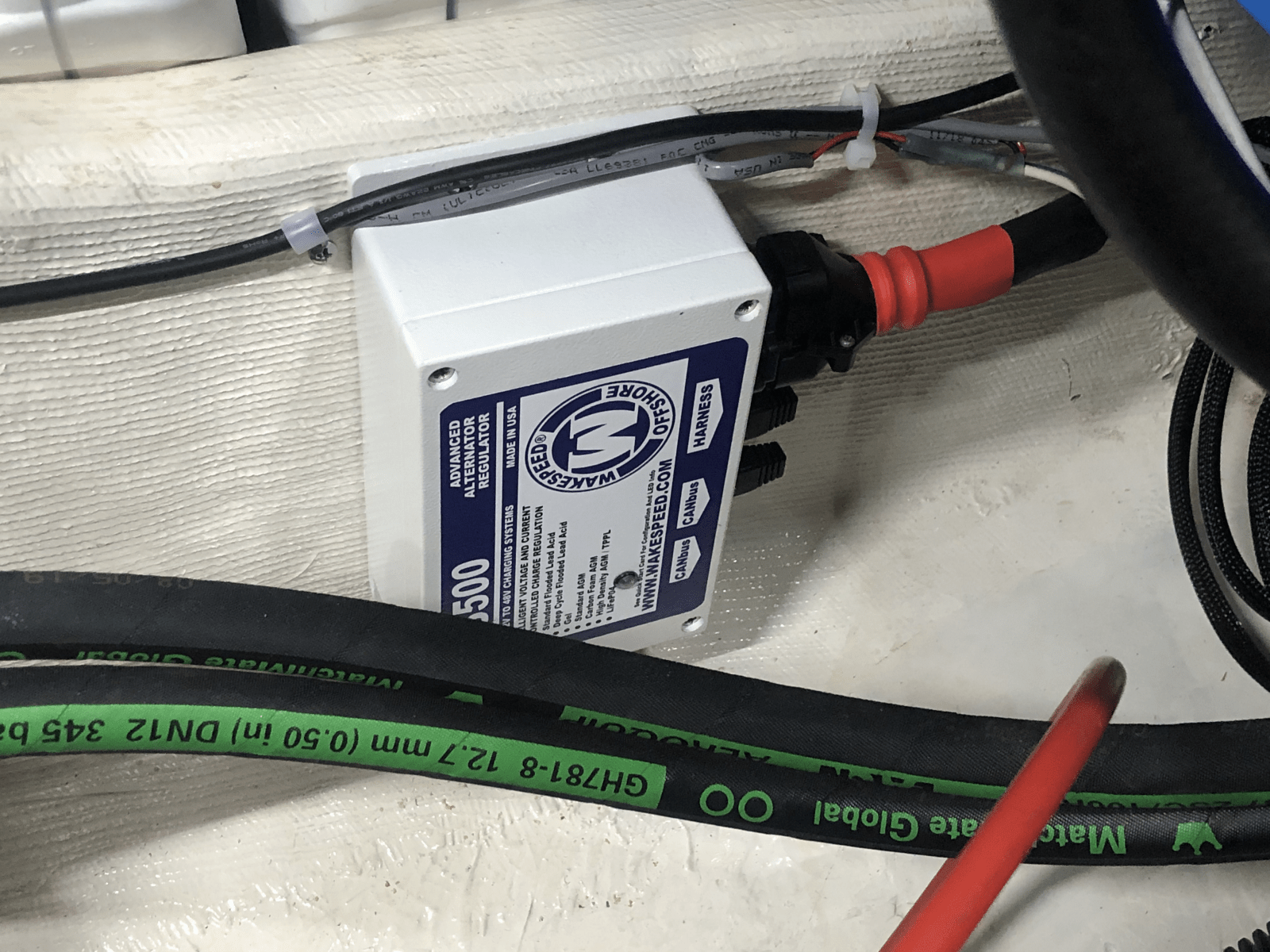
How Wakespeed’s WS500 alternator regulator solves complex charging issues, now with NMEA 2000 UPDATE
It’s hard to imagine getting excited over a mundane appliance such as an alternator regulator, but there is a lot to like about Wakespeed’s WS500 device. For me, the primary reason is that this regulator has addressed a gnarly charging problem on Bliss, our 40’ pilothouse trawler. It may help with yours. Let me explain…
A few years ago, deciding to finally do something about uncomfortable rolly passages on our round bottom full displacement trawler, we swapped our 5 kilowatt AC genset for a SeaKeeper 5 gyro stabilizer. The generator had to go to create sufficient space for the new stabilizer. This resulted in an interesting dilemma since 2000 watts of AC power is required to run the gyro, but the only device onboard capable of generating such power was the genset. And that had to be removed to make room for the stabilizer. To support the gyro’s current requirement, we had to upgrade the DC generation system by adding two 250 amp MGDC high output alternators to our single 100hp Yanmar diesel engine. Installation of the stabilizer is very nicely described by Ben Ellison in a previous Panbo post.
Bliss charging issues
This is where the problems start. Initially, we installed Balmar multi-stage regulators. What we did not understand was that almost all such advanced (or “smart”) regulators use battery voltage and percent field current to determine the battery bank charge state, and although the technique has worked well for decades on many boats, it can cause problems on vessels like Bliss with significantly fluctuating electrical demands.
Unlike traditional alternator regulators that cap alternator output to constant voltage (usually between 13.5-14.5V), “smart” regulators have been designed to minimize charging times by using a multi-step approach to implement specific charging regimes recommended by the battery manufacturer. For example, the following graph shows the recommended optimized charging sequence for my new Victron Gel batteries.
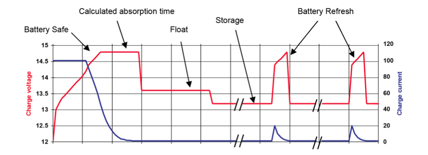
“Smart” multi-stage chargers implement these sequences by varying field current while attempting to monitor battery charge state. Traditionally these regulators use voltage and percentage field output to determine the charge state of the battery bank. Although a detailed description of “smart” regulator technology is beyond the scope of this article, Balmar’s site describes their charge sequence tech very nicely.
Consider how the popular Balmar MC-614 used to function on Bliss as configured for our Gel batteries. It drove an acceptance voltage (also called absorption voltage) of 14.2V with a field trigger of 65% max field amplitude. When going through its charge cycle, the regulator starts in “bulk” mode, where the alternator is told to output as much current as it can until it reaches the acceptance voltage of 14.2V. Once in “acceptance” mode, the field current is slowly dropped down until the output reaches 65% of its max. The 65% mark triggers a ramp down to a float voltage of 13.8V, where everything remains until the engine is stopped. If the regulator, while in “float” mode, has to increase its field output to more than 65% in order to maintain voltage, the regulator re-enters bulk (or accept) phase restarting a charge cycle.
The problem with this setup on a boat that runs continuous heavy loads (like mine) is that the battery may be charged to full capacity, but the electrical demands on the house are so high (e.g., running a gyro that requires 2000 watts) that the 65% trigger point is never met. The regulator never enters the “float” state, and the batteries are grossly overcharged. It took us several weeks to discover what was happening to us, resulting in the destruction of our 1800 Amp/Hr sealed battery bank. An expensive lesson, to say the least…
When at anchor, not running the gyro or other heavy house loads, we discovered that we were still having charging issues. On Bliss, we have 1000 watts worth of solar panels allowing up to 80 amps of charge at peak times. Under these peak conditions, the regulator hits the 65% field threshold prematurely, causing the system to enter “float” mode before the battery bank is fully charged. Grrrr….
Finally, there is the issue of RPM. The amount of current created by the alternators is a function of the field provided by the regulator and the engine RPM. If the engine is at a slow idle speed, then the alternator drive field must be increased to yield more charging current. With large battery banks, this can cause issues if you (like me) start an at-anchor charge cycle at fast idle and then slowly reduce the RPM (to save fuel and load the engine) while the current requirements drop. This causes the regulators to possibly overcharge your batteries because, once again, with a large battery bank, the 65% field threshold is not met, and a transition to the “float” state never occurs.
Solar panels, large loads, varying RPM, etc. confuse most regulators causing batteries to be either under or overcharged, resulting in shorter life expectancy and poor performance.
An interim solution was to reprogram the regulator for a lower acceptance voltage and a field threshold of 75%. This allowed us to motor for long distances without frying the batteries, and thus preserving the capacity we had left until we could replace the bank. However, at anchor, we could not charge our batteries efficiently because the system then floats too soon. Very frustrating.
Bliss discovers the WS500 (an Aha moment)

When I discovered that the Wakespeed WS500 uses an amp shunt to measure the actual current going into the batteries instead of using percent field thresholds to manage its charging algorithms, I was instantly sold. I bought two of them straight away.
The ability to measure the current going into the battery bank separates this regulator from the pack. That is not to say that there are no other features that make this regulator quite desirable, but we will get to that later.
With the WS500, you don’t have to worry about heavy house loads, solar panel output, and RPM affecting the charge cycle. The regulator always does the right thing. For my new Victron Gel 1855 Amp/Hr bank, this means that when the current going into the batteries hits 4% of the bank capacity ( that is 1855 Amp/Hr * 0.04 or 74.2 amps) the system instantly goes to float. When in “float” mode, if 20 amp/hours were to be consumed out of the battery — like when a really heavy house load is turned on that alternators can’t keep up without requiring helpt from the battery bank — the system restarts a charging cycle. No-fuss, no mess… the regulator just does the right thing always.
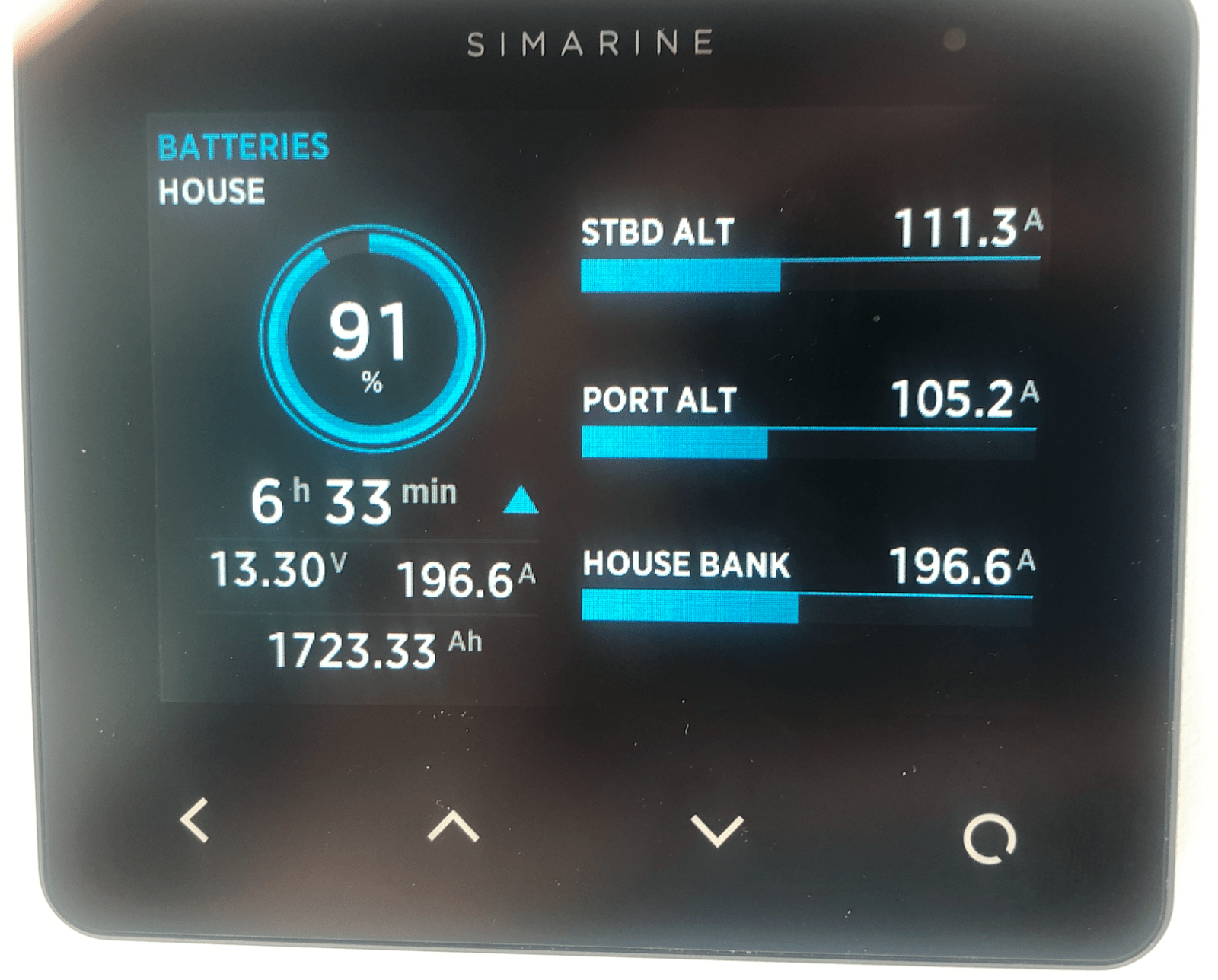
I love the following images. They show how Bliss now moves through the charge stages until she’s happily motoring along while generating 160 amps of current to run the house and the gyro while the batteries are in float mode absorbing 47 amps. The battery bank would continue to float at 47 amps, even if I were to start the microwave and the washer dryer and/or other heavy loads. It’s a beautiful thing to see in action! (More on Simarine power monitoring here.)
Bulk Charging 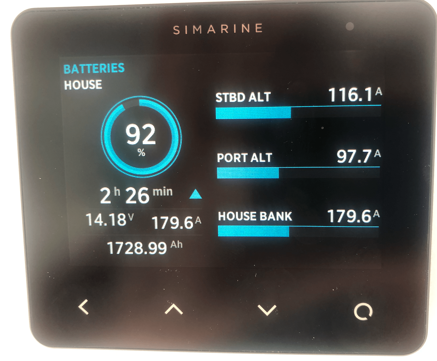
Acceptance Mode 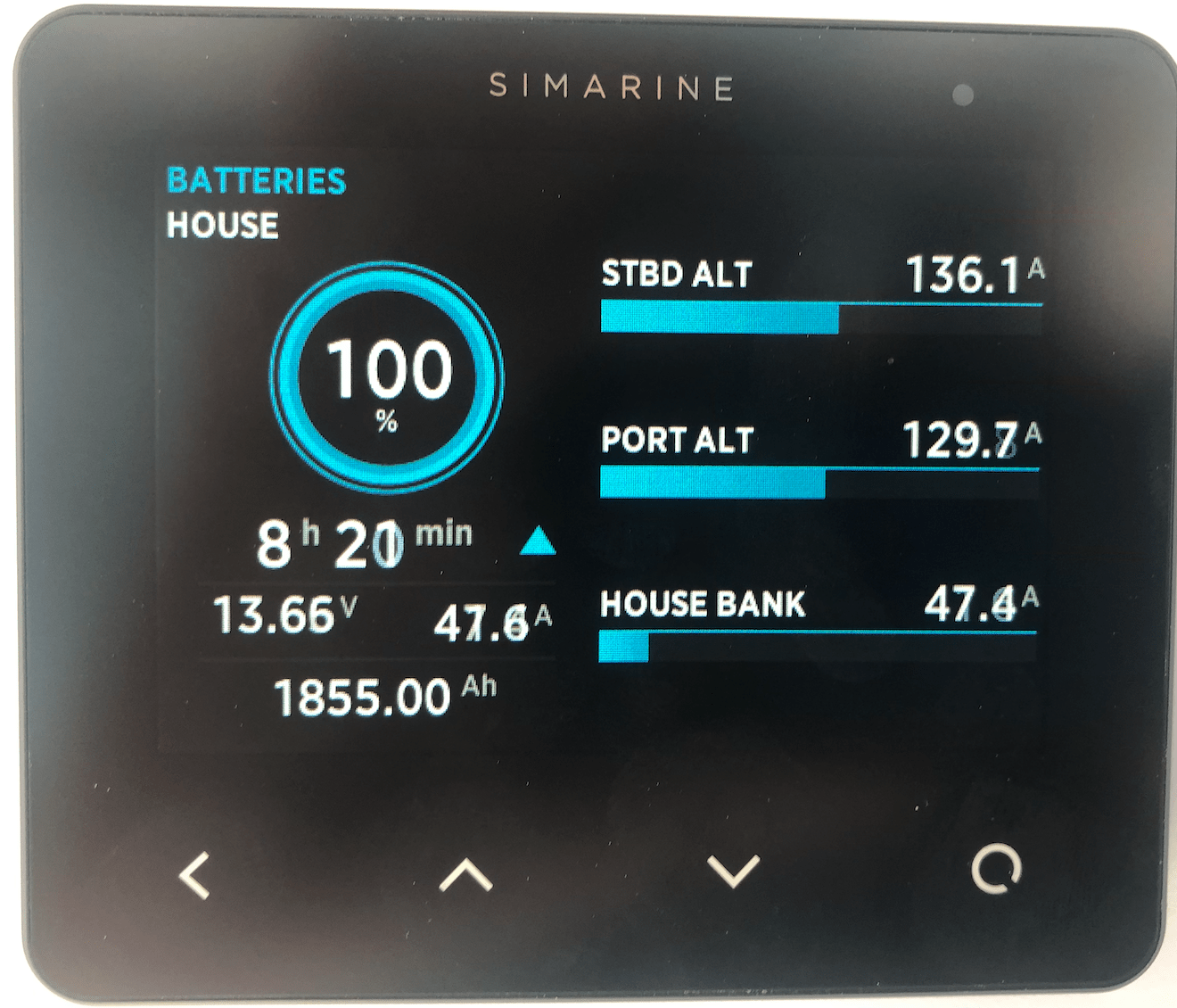
Float State

Installation and basic WS500 configuration
Installing the WS500 is as simple (or complex) as any other regulator, with the addition of 2 wires that go to a current shunt on the negative return to the battery bank. Battery voltage sense, regulator power, ignition, field, and, etc. are the same as in most any other smart regulator. Following is the wiring diagram for the regulator.
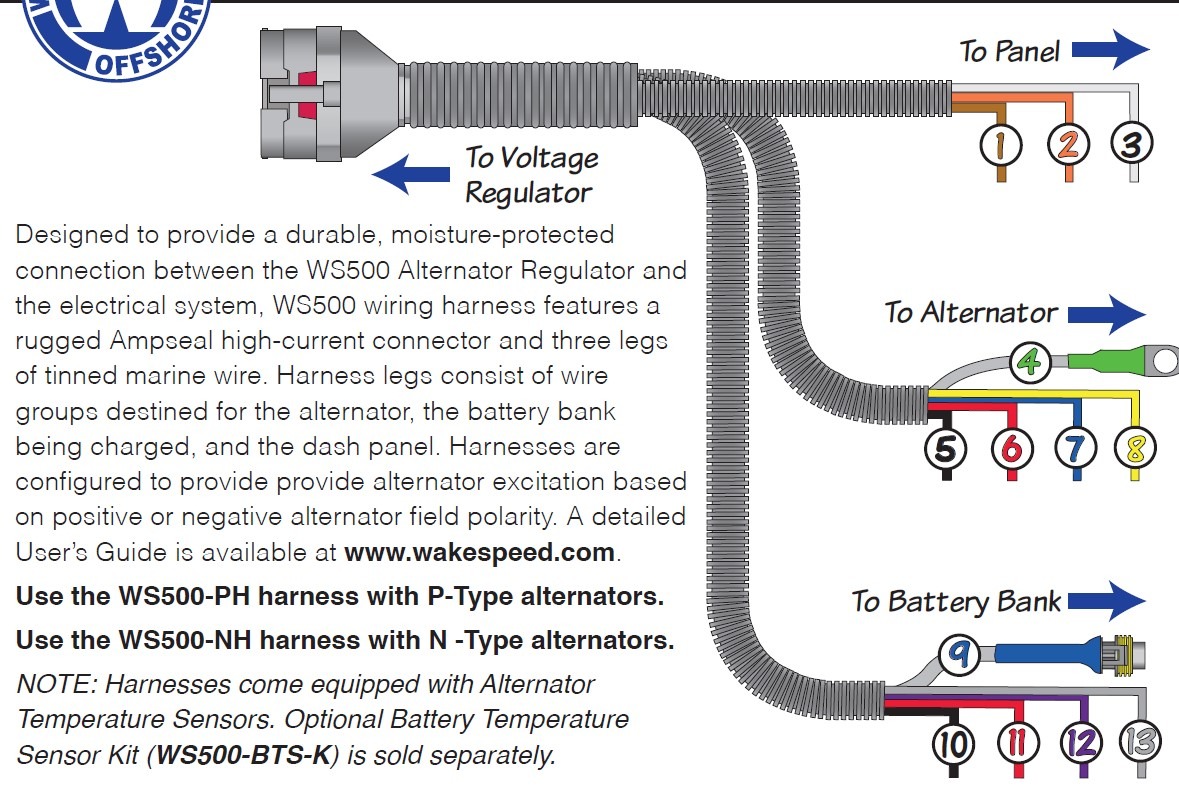
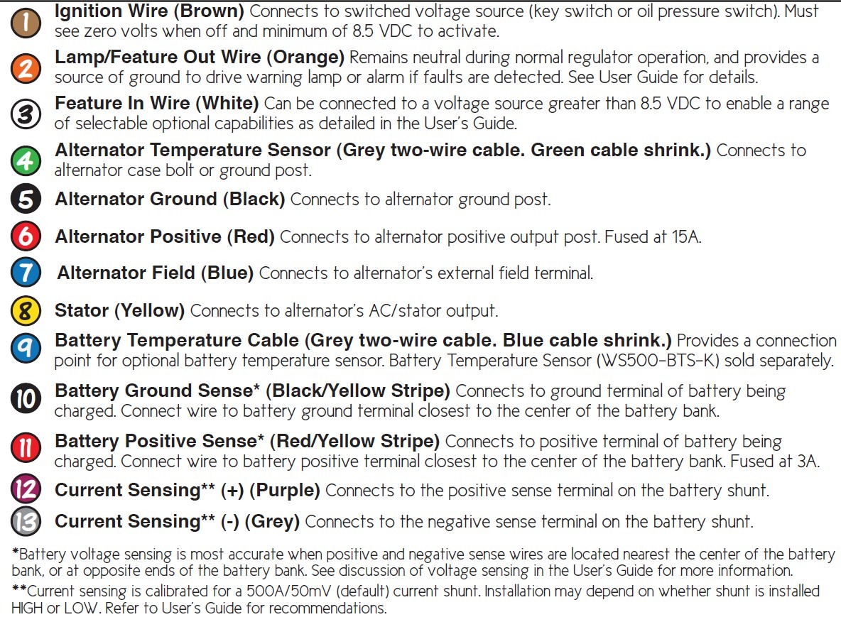
The harness that comes with the regulator includes a temperature sensor for the alternator but none for the battery bank. Users will need to supply this if they want the regulator to adjust charging voltages and current based on battery temperature (something you are encouraged to do). Care should be taken to get the polarity of the current sensor correct. If wired backward, the regulator will not work, although there is a way to change the polarity in software using the advanced configuration mode (more on this below).
It is important to note that when connecting the wiring harness to the regulator that the fuses to both the sense and power positive leads are removed. Under most conditions, nothing serious will happen if you forget, but it is possible to damage the regulator if the positive leads establish a connection before the ground leads do.
The WS500 can provide up to 30 Amps of field current output compared to others that only support 15 Amps. 30 Amps allows one regulator to control multiple alternators or specialized alternators requiring very high fields. On Bliss, each MGDC alternator requires 8 amps for maximum output. So while I used to throttle down the maximum field to 90% to maintain the 15 amp limit — and avoided blowing an internal regulator fuse — now I can get full output from both alternators at once. I still find this remarkable. That is 6 kilowatts of DC power out from my small 100hp Yanmar while motoring. More than we ever got out of our 5Kw Kohler genset.
Although the WS500 does have an extensive configurable feature set available through a programming interface (more on this below), most users will find that configuring the unit via 8 dip switches will do the job. Entering the battery type and the battery capacity is all that is required. Note that the regulator expects a standard 500Amp/50mV battery shunt to work correctly. But there is no problem piggybacking off of one that you might already have for your house battery monitoring system (though if your shunt is something other than 500/50 or the polarity is reversed, then the advanced configuration will be required to modify the setup). Following is a description of the dip switch settings from the manual.
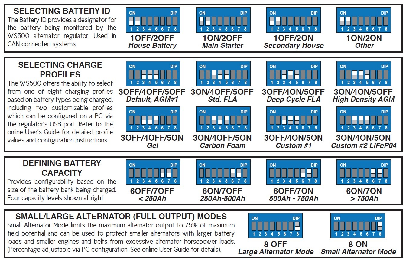
Of particular note is switch 8, which limits the current output to 70% and is meant to protect small engines from being overwhelmed by large alternators. It can also be used initially to make sure things are working as expected before turning on the full spigot. And all of the switch settings can be overwritten via the advance configuration mode discussed later on.
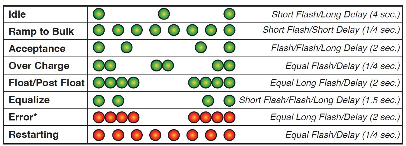
One LED on the front of the unit provides status codes via blink patterns. The following enumerates the different error codes and statuses for the regulator.
For most users, that is pretty much it. Connect the ignition, alternator power, voltage sense, and battery shunt current sensing wires. Hook up the alternator and battery temperature sensors. Finally, configure the switches for battery chemistry and Amp/Hr capacity, and off you go to worry-free battery charging nirvana.
A configuration wish list
Having already blown a large battery bank, we wanted better control over the charging sequence. So using the switch settings was not enough. Additionally, we now had the problem that when motoring at slow RPM with low batteries, the alternators consumed most of the engines available horsepower, making the engine sluggish. Specifically, we wanted to modify the regulator settings to:
- Force float via a switch on the dash to prevent overcharging of the battery bank if the regulator misbehaved. As it turns out, this was an unnecessary concern but nice to have for us paranoid types.
- Force alternator output to 30% of maximum via a switch when motoring at slow RPM so that most of the engine power goes to propulsion.
- Implement Victron gel battery specific charging recommendations, including a “post-float” maintenance mode when making multi-day passages.
- Specifying the exact size of the battery bank, max current allowed into the bank, and trigger amperages for entering and exiting the float and “post-float” states.
Fortunately, with some additional wiring and advanced programming, the WS500 can deliver on all of these requirements.
WS500 advanced wiring
First, we tackle the wiring. Here is a picture of hardware switches and LEDs installed on our dash to support the additional functionality.
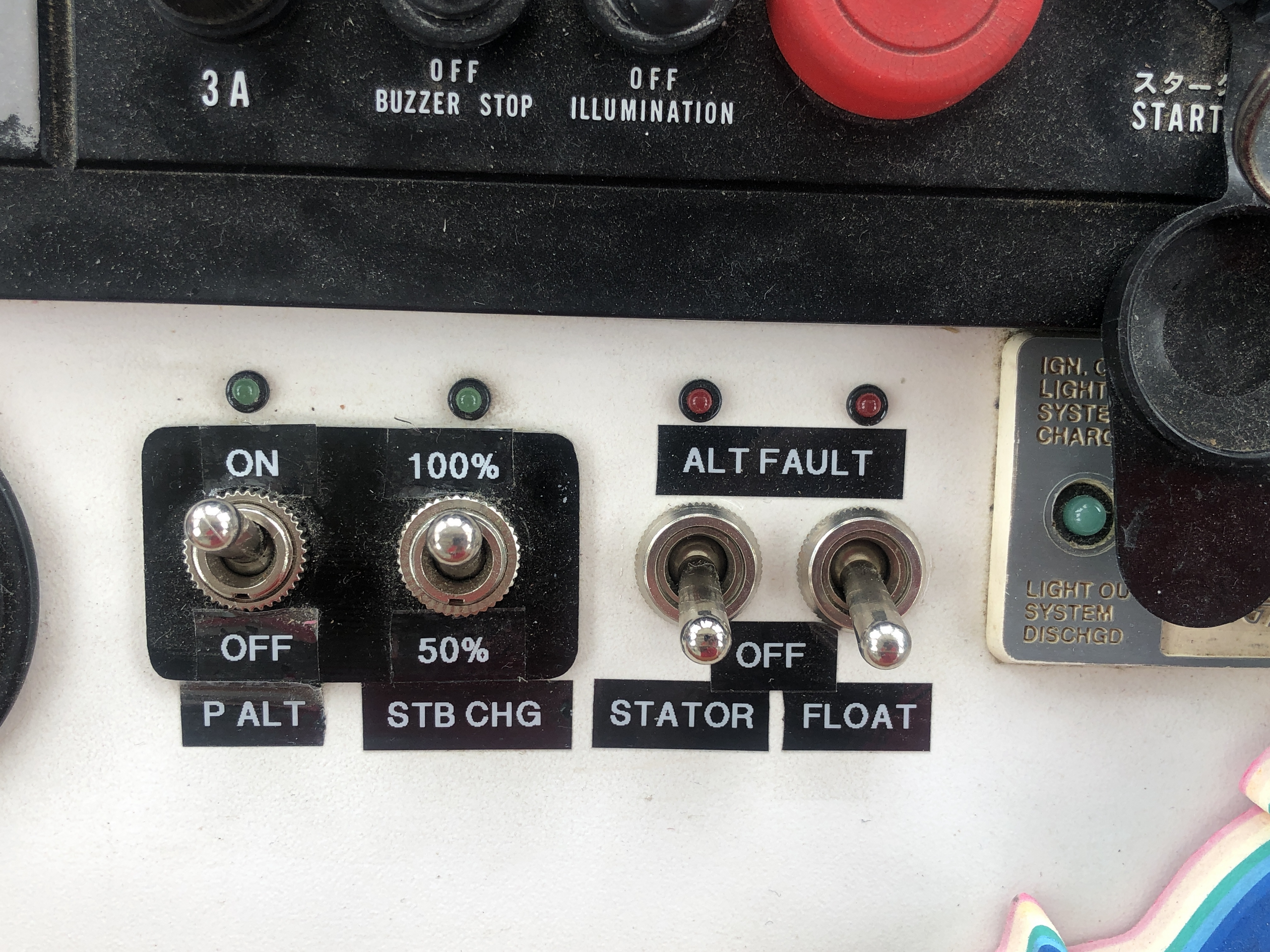
On-demand reduced alternator output can be forced by shorting out the alternator temperature sensor, in our case by running two wires — one from each lead of the alternator temperature sensor — to a switch on the pilothouse dash . By default, this reduces the alternator output by 50%. For us, however, reducing power by 50% was not enough.
The power curve for our 100 HP Yanmar 4jh2 engine does not show available HP at 600 RPM, but it’s not much. Meanwhile, 4 HP is required for every 100 amps of alternator output, and our system, as configured with a 3:1 pulley ratio, is capable of producing 300 amps at 600 RPM. In other words, at full alternator output when idling, the alternators demand 12HP out of the engine, which leaves close to nothing for propulsion.
So while a 50% reduction to 150 amps (6HP) was not enough for Bliss, the WS500 allows for modifying the output power when in reduced mode via a software setting, and it was not a problem to decrease the output further to 100 amps or 4HP at 600 RPM.
Note that WS500 has a pull-back feature (PBF) designed to specifically address the problem of large alternators overpowering small engines at low RPM. PBF uses the regulator’s stator input to measure engine RPM. The PBF can be adjusted to reduce output based on RPM at near idle speeds. We opted not to use this feature because while useful in motoring situations, we wanted all available engine power to go to charging when at anchor. So for us, a switch makes more sense.
I have heard of other systems using the transmission shift control to activate a relay that then enables alternator stator input into the regulator. This would allow switching between reduced and full power at idle based on whether the propeller shaft is rotating. Although we may experiment with this at a later date for now, we are happy with our manual at anchor/underway mode switch. The stator switch on the dash enables RPM input into the regulator should ever want to use PBF.
Similarly, the force float feature was also easy to set up because the WS500 sports a Function IN line that can be programmed to support this. Running a single plus wire from the dash to the Function IN regulator input accomplishes this very nicely. Although we have never had to use this feature yet, its nice to have.
The ALT on/off switch was initially intended to actuate the ignition wire on the regulator, allowing us to totally disable charging while still keeping the dash alive. At the moment, we have the ignition wired to the key on the dash, so starting the engine enables the regulator. I see no need to implement the ALT on/off switch. However, it’s nice to have it should we in the future wish to (for some reason) disable the alternator while motoring.
Finally, the dash lamps are wired to the regulator so that problems and error codes can easily be detected.
WS500 advanced configuration and programming
If custom programming is required to finalize a WS500 installation, it may seem daunting at first, but it’s really not too bad. To program the unit, you must first remove the cover to access the USB port, which is also required to access the configuration dip switches adjacent to the USB port. (These are the switches discussed above for basic configuration without programming.)

The USB port is the plugged into either a windows PC if users want to use the programming tools provided by Wakespeed or to the OPE Tether, a WiFi access point device discussed in detail in a bit.
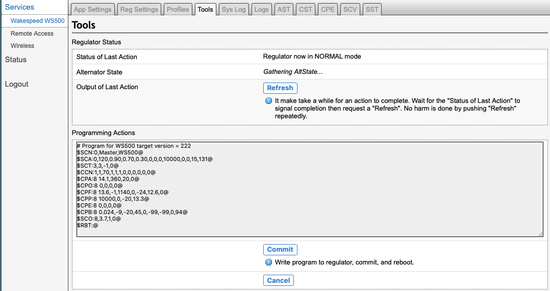
Before diving into the mechanics of programming, let me first share the following, which is the WS500 program used to configure Bliss‘s regulator:
#Program for WS500 target version = 222
$SCN:0,Master,WS500@
$SCA:0,120,0.90,0.70,0.30,0,0,0,10000,0,0,15,131@
$SCT:3,3,-1,0@
$CCN:1,1,70,1,1,1,0,0,0,0,0,0@
$CPA:8 14.1,360,20,0@
$CPO:8 0,0,0,0@
$CPF:8 13.6,-1,1140,0,-24,12.6,0@
$CPP:8 10000,0,-20,13.3@
$CPE:8 0,0,0,0@
$CPB:8 0.024,-9,-20,45,0,-99,-99,0,94@
$SCO:8,3.7,1,0@
$RBT:@
Basically greek! A description of what all this means is found in the WS500 programming manual found at wakespeed.com. The 0.30 field in the $SCA:0 line, for example, means reduce the power output to 30% when the alternator temperature sensor is shorted.
Wakefield provides Windows-based drivers and DOS-style command-line tools to transfer programs like the one above to the regulator. They also offer a configuration guide with detailed instructions on how to program the units and several templates for predefined configurations. The programming sequence is as follows:
- Download the configuration guide and drivers from www.wakespeed.com
- Plug a USB cord (not supplied) into a windows computer
- Install the USB drivers
- Use Notepad (or some other text editor) to create or modify a WS500 program like the one listed above. Then save the text file into the directory where the Wakespeed tools were installed.
- Run the Windows command-line editor (cmd.exe) and change (cd) into the Wakespeed program folder.
- Run the Wakespeed console-based file transfer utility.
- Check for errors and repeat steps 4-7 as needed.
The process is not too complicated if you are technical and accustomed to coding and using command-line tools.
Introducing the OPE-Tether WS500 accessory

Fortunately, however, there is a much more straightforward and better way to program these regulators using the OPE-Tether, a small WS500 add-on WiFi access point sold by Ocean Planet Energy and providing the following features:
- Mobile-friendly web access to the WS500 via WiFi. No device drivers are required. Works with all web able mobile devices. IOS, Android, Windows, Mac, and Linux compatible.
- Connectivity to regulator via USB or the regulator’s external RJ45 CAN bus connector.
- Easy firmware updates for the WS500 regulators.
- Simple form-based web programming of WS500 regulators.
- Realtime monitoring.
- Logging of all regulator parameters on the internal SD card.
- Connectivity to a vessel network via Ethernet or WiFi.
- Tethering via mobile phone for remote WS500 support from OPE.
- Powered by 9-35V DC. AC/DC adapter is included.
The vital thing to note is that this device requires no specialized knowledge of programming, command-line editors, or text editing to access the full WS500 feature set. All that is needed is a WiFi-enabled computer or device and a web browser.
Time for a disclaimer. I am the creator of the Tether. After purchasing two WS500’s for Bliss, I thought the product deserved a better way for the community to access all of its features.
A full review of the Tether is beyond this article’s scope, so I will focus on the programming of 2 features to give you a feel for this tool. First, we will modify the configuration to provide the regulator with a name and specify the size of the battery bank to accurately define the “float” state and enable the float dashboard switch. After that, we will program the float and “post-float” state settings and activate the program on the regulator.
Before jumping into programming mechanics, let’s discuss the “Remote Support” feature, one of the most powerful things about Tether. It allows a user to tether their WS500 regulator(s) via their cell phone (in hotspot mode) to OPE technicians, who then have full access to the device. So if you run into problems, an expert can diagnose and correct your installation. The Tether’s quick start guide provides details on the tethering process.
Programming the WS500 with the OPE-Tether

After powering on Tether and wiring it to the regulator, you connect to the system via WiFi, login, and then browse to the “Regulator Settings” tab to start the programming process. You then enter the desired settings and save them. Battery Size, system voltage, regulator name, enabling the “Function In” line are defined in this first screen.

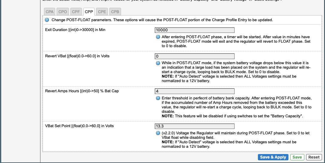
Next, while still in the “Regulator Settings” section, you browse to the CPF (float state parameters) and CPP (post-float state parameters) tabs to enter the desired values. Battery maintenance voltage for the given state, time duration, and exit conditions are specified here. Of particular note are the state exit parameters. We determine that we are to exit the “float” state after 5% of the Amp/Hr capacity of the battery bank has been used or 4% for the post-float state. Settings are then saved for transfer to the regulator at a later date.
To transfer the new settings to the regulator, we now navigate to the Tools tab and push the program button. We then (if we want) verify that the generated program is to our liking and if all is well, push the “Commit” button to transfer it to the regulator. We then wait for confirmation that the program was accepted. The regulator will restart automatically, and the new settings will take effect.
As easy as 1.. 2.. 3..
The Tether UI is pretty much self-documenting, so it’s just a matter of spending time and experimenting with the settings to perfect your regulator setup. When done, you can use the profiles tab to save these settings with a specific name and comment. The Tether can store many profiles, which makes it handy for installers moving between customer boats. Users can also download the settings to their computers, share them with others by emailing them as attachments, and then upload them into a different Tether. This feature can be used, for example, to contract OPE or another vendor to create and email you a custom configuration for uploading to your WS500.
There are many, many more things we could discuss, but I believe that this will give you a good idea of what is required to configure the regulator.
More WS500 features
Before we go, I want to mention a few additional WS500 features not discussed in detail here.
WS500 supports the connecting of multiple regulators via the RJ45/CAN bus on the outside of the units using standard Ethernet cabling. In this configuration, one of the regulators automatically takes over as the master and controls the other regulators as slaves. This allows for multiple regulator/alternator setups to charge one large battery bank in a unified way, which can a nice feature on multi-engine vessels. Engines/regulators can be turned on and off at will, and the system dynamically reconfigures itself to do the right thing.
For users with large alternators and small engines, the American Power Systems, Inc version of the WS500 (called the AP500) has a “white-space mode” that augments the pull-back factor previously described, allowing you to specify alternator output for 8 RPM ranges. The feature allows, for example, the implementation of a table such as:

Finally, for those wishing to see battery state and charging information on your NMEA 2000 displays, the OPE-Tether will soon have an option that bridges WS500 information to a vessel’s N2K instrument network. I will add more information about it in the comments section below as the feature becomes available.
Summing up
Its hard to believe something as uninteresting looking as this can be so important. But it is. I hope you see now why the excitement.
Good luck and happy charging — Luis Soltero, MV Bliss, Currently in the Chesapeake
WS500 to NMEA 2000 update
8/1/2020 — I’m happy to report that the WS500 installed on Bliss is now sending valuable data to my NMEA 2000 network. Here’s the story:
The CAN bus networking used by the WS500 supports the following data layer protocols:
- J1939 — used for engine information, including RPM, and common in cars, trucks, and newer diesel engines.
- RV-C — used mostly by manufacturers of DC and AC power systems, such as battery management systems (BMS) meant to interface with other electronics.
- NMEA 2000
Given that NMEA 2000 and RV-C are built on top of the J1939 protocol, there is no electrical impediment for connecting the WS500 directly to your vessel network, and this can be accomplished by making a special cable with RJ45 to DeviceNet connectors, or by purchasing your WS500 harness from Ocean Planet Energy, which comes with a CAN bus DeviceNet connector.
Caution: The WS500 is not certified by NMEA for use on N2K networks, and it may never be. NMEA specifies that CAN bus interfaces connected to N2K networks must be optically isolated, and the WS500 is not. Also, NMEA specifies that only valid N2K data frames are to be used on the network while the WS500 uses non-N2K frames to communicate with other WS500s, plus BMS’s and other non-N2K devices. Like N2K, RV-C also uses PGNs for its sentences. There is some overlap between the N2K vendor-specific PGN range (130816 … 131071) and some RV-C PGNs, which may cause conflicts should the vessel instrumentation use some of these.
So, although it’s unlikely that connecting the WS500 directly to your N2K network will cause issues, be aware that this is not approved or sanctioned by either NMEA or by Wakespeed. Brave souls can try it, and if it works, great. But there are several ways to get better, cleaner, and safer WS500 data onto your vessel’s N2K network.
First of all, an N2K-to-N2K bridge such as the Yacht Devices YDNB-07 or the Maretron NBE100, will do the job. These devices automatically prevent non-N2K traffic on the WS500 side from being propagated on the vessel’s N2K network side while also electrically isolating the CAN bus (and the Maretron bridge is NMEA certified). Other N2K bridge models may do the same but make sure to check the documentation before you purchase to ascertain that they support filtering.
N2K bridges, in their default configuration, will not resolve RV-C PGN conflicts with proprietary N2K PGNs should any exist on the network. However, both of the bridges listed above support custom filtering. For the NBE100 you use a Maretron USB100 Gateway and their Maretron N2KAnalyzer program to block all traffic except the required whitelist sentences (see PGN list below). Creating filters on the Yacht Devices bridge involves creating a text file with program statements stored on an SD card and then inserting it into the device, as explained in the YDNB-07 manual PDF. Yacht Devices technical support was kind enough to provide a YDNB-07 configuration script that should work with the WS500 (after you change the file name to “YDNB.CFG”), although neither Wakespeed nor I have had an opportunity to test it.
Alternately, the OPE-Tether discussed in previous sections above can be purchased with an Ethernet-to-N2K adapter cable that plugs into the Tether’s LAN port providing plug-n-play conflict-free N2K network bridging. (As a reminder, I am the creator of the OPE-Tether.) Like the YD and Maretron bridges above, the Tether isolates the networks and only passes bonafide N2K traffic. Tether passes only N2K sentences sourced from the WS500 and no others, avoiding network conflicts. Additionally, Tether provides WiFi connectivity to the programming of the WS500 and realtime monitoring of over 100 parameters (i.e., much more than is available over N2K).
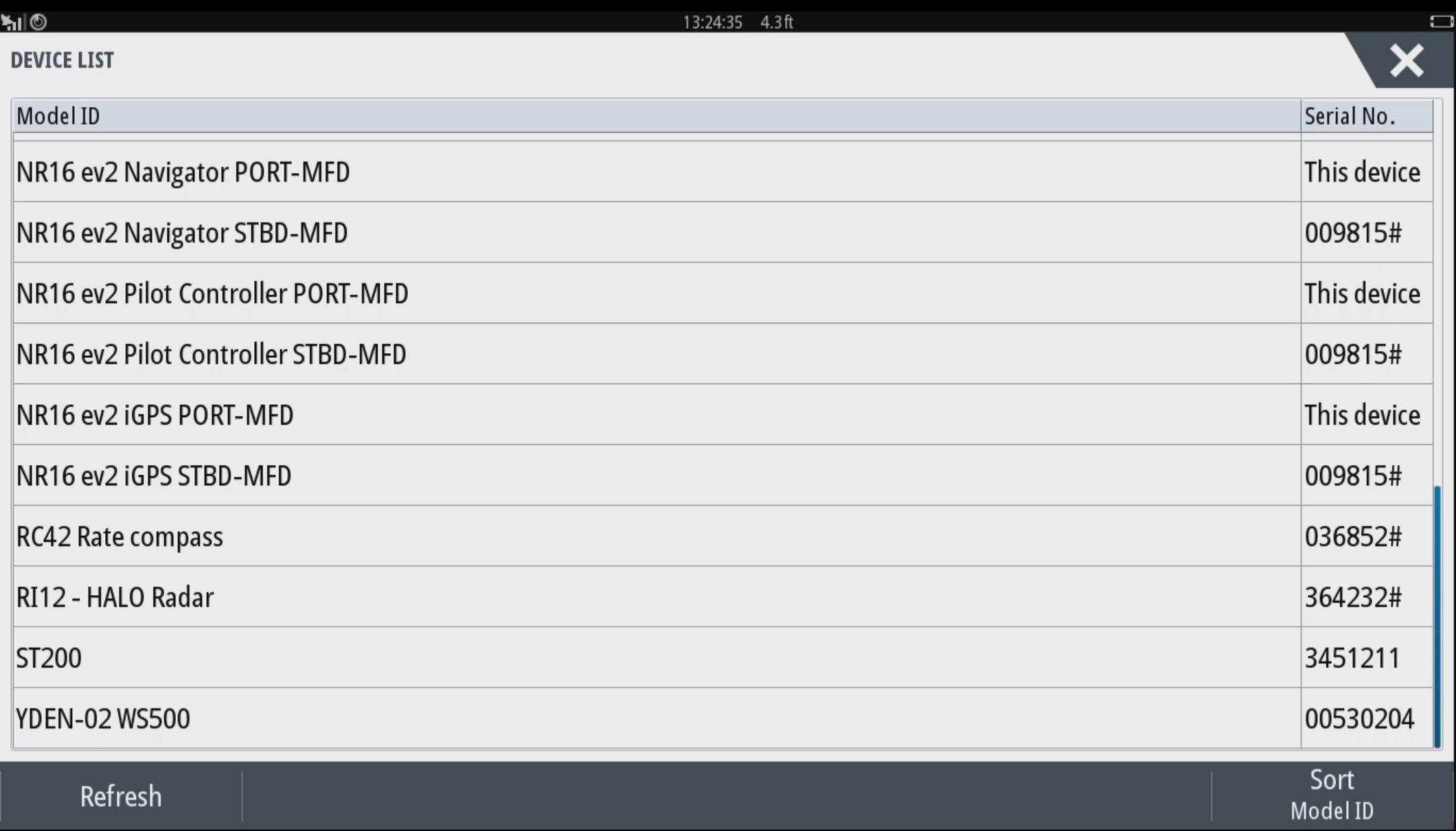
Here are a series of screen captures showing how my Simrad NSS16 evo2 MFD can list the N2K devices it sees on the network as well as the data it’s able to interpret.

List of N2K devices seen by NSS evo2 on Bliss 
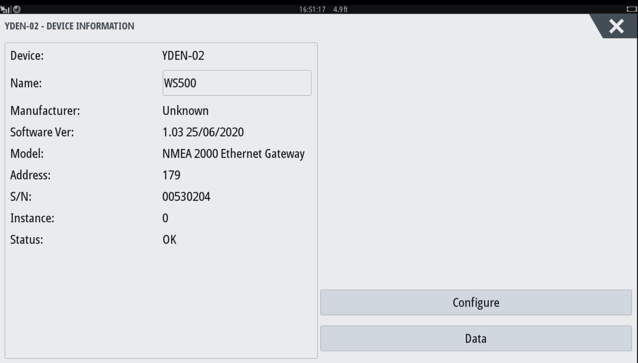
Detail on OPE-Tether delivering WS500 info 
Specific WS500 data seen on network
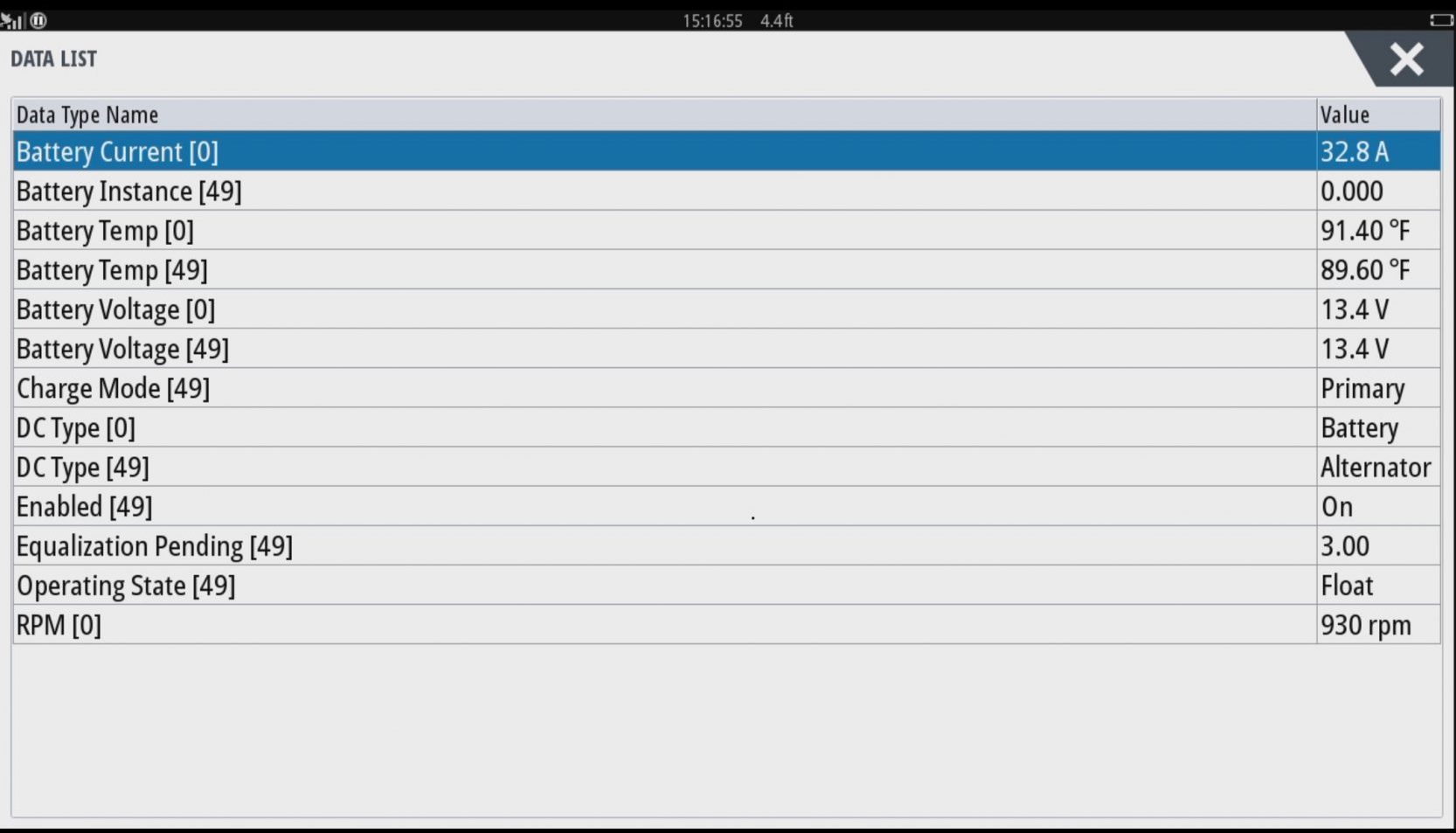
The lower data screen does not show the specific PGNs involved, but does show the data fields that the NSS understands from them, along with what are known as device and data “instances” in brackets. The default N2K data (and device) instance is 0 and the PGNs that use data instance usually involve boat equipment that there’s often more than one of, like battery banks and engines. So the Battery Current [Battery Instance 0] above showing a current value of 32.8A is the amperage going into Bliss main battery bank. The story is similar with RPM [0] and if Bliss was twin screw, there could be an RPM [1] data line (with the normal N2K instancing of 0 = port engine, 1 = Starboard).
If you dig deeper into NMEA 2000 terminology, several PGNs with Battery in their title can actually reference other DC sources and be given DC Types like Alternator or Solar Cell, and you can see that in action above. The WS500 gives the alternator a data instance (called Battery or DC Instance) of 49 and thus all fields marked 49 are about Bliss’s alternator. In other words, the Battery Temp [49] of 89.60F is the temperature of my alternator case just getting warmed up on an already hot Chesapeake Bay day. It can go much higher and that’s why I’d like to keep a close eye on it.
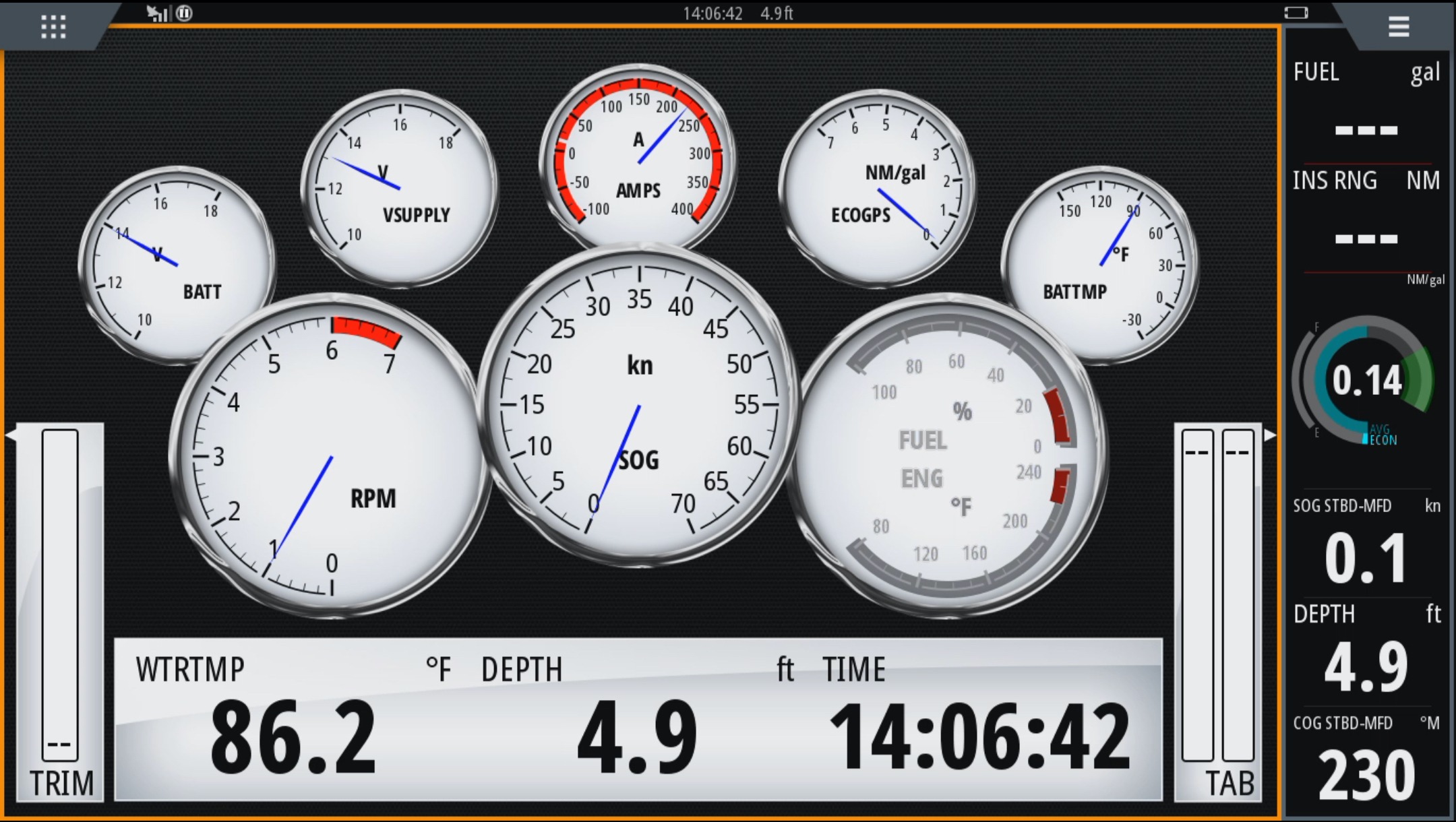
Most N2K MFDs and instrument displays let users choose among data sources for gauge information if choices exist on the network, at least to some degree. For example, my Simrad NSS16 Evo2 above is showing BATT V, AMPS, BATTMP, and RPM all sourced from the WS500 through the Tether. So I have to choose between Battery Instance 0 and 49 (the alternator V, Amp, Temp) because the MFD can not display the same general type of data from two sources at once.
Fortunately, I have two NSS displays that allow me to configure one with the battery and the other with the alternator info. But be aware, as I’ve demonstrated, that even if you can see data on an N2K display’s diagnostic screen, you may not be able to show it wherever you want. (Also note that VSUPPLY is the voltage actually seen by the NSS, which is quite different than the battery charging voltage.)
My understanding is that NSS evo3 addresses this data display problem and also offers custom labeling of data fields so that BATTMP [49] can be seen on screen as something like ALT TMP. I also know that Ben Ellison now has a wealth of similar Victron generated DC PGNs — battery, inverter, and solar charger — on Gizmo’s network, and Panbo readers will eventually hear about how they display on Furuno TZT2, Simrad GO5, and Maretron screens.
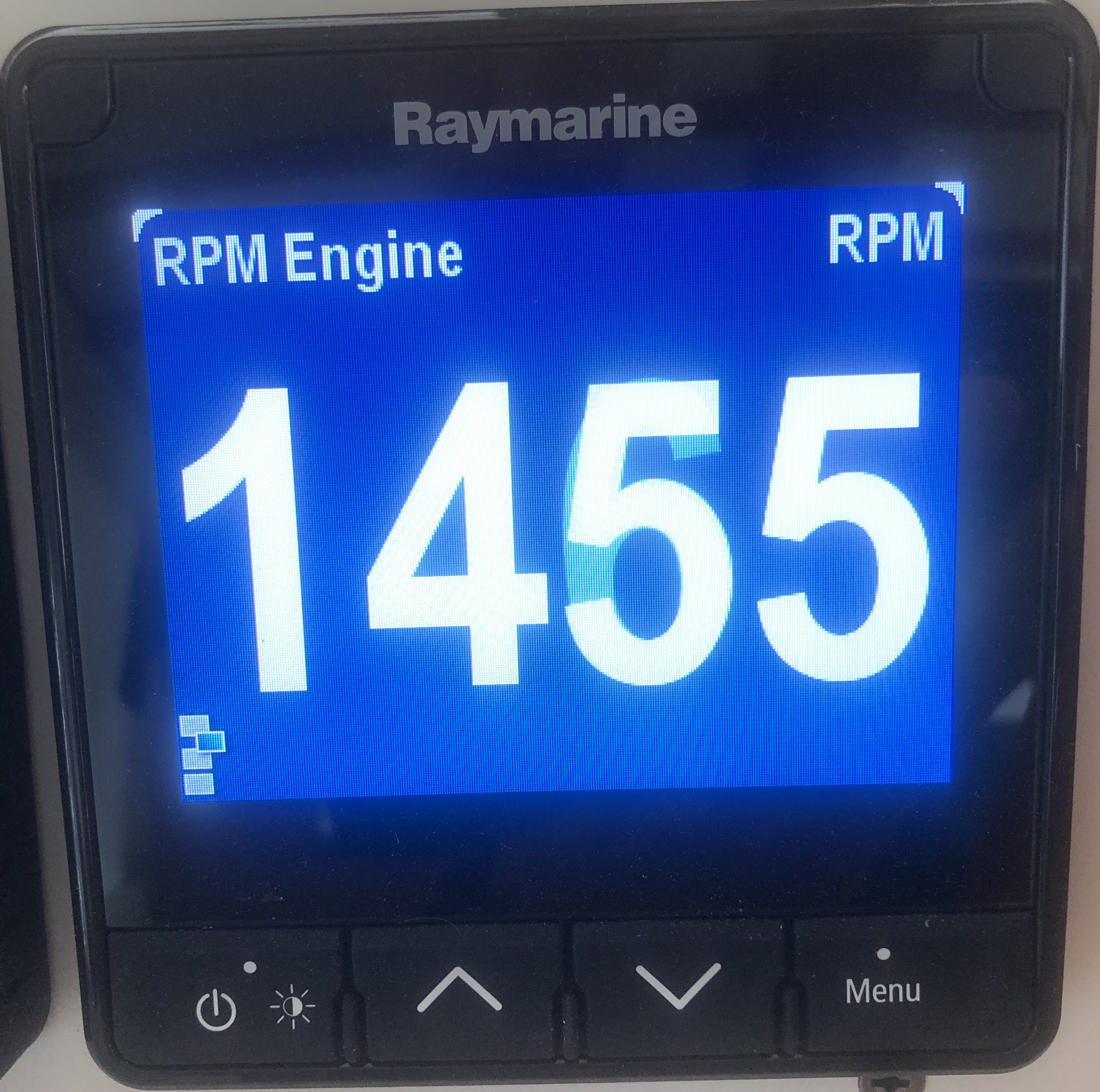
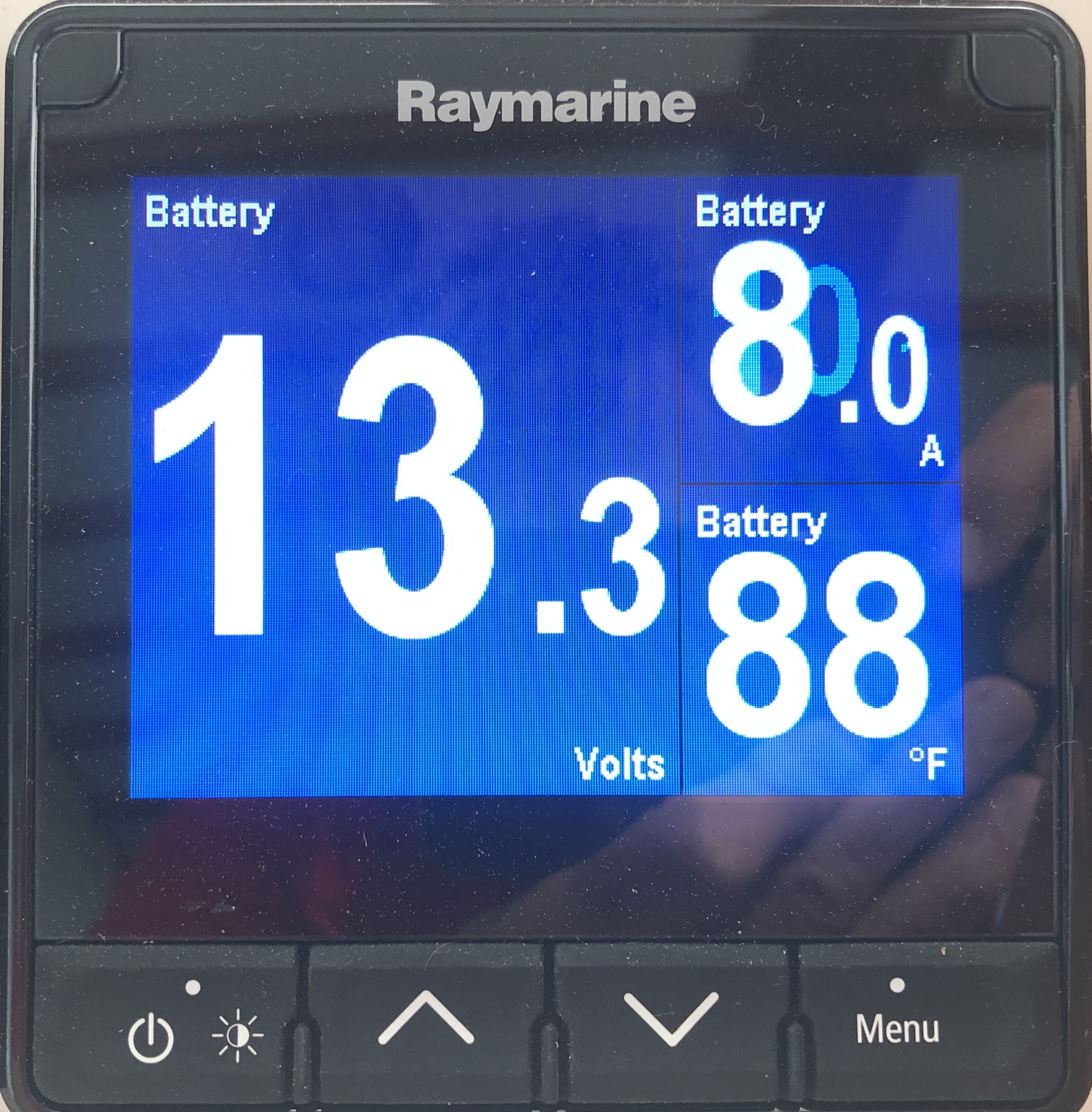
Here are pictures of my Raymarine i70 display showing engine RPM and Battery status sourced from the WS500/Tether.
The WS500 supports the following N2K PGNs:
- 127488 – Engine RPM
- 127506 – Detailed DC Status including the State of Charge, State of Health, Time Remaining, and Ripple Voltage
- 127507 – Charger Status including the Operating State, Charge Mode, Charger Enable/Disable, Equalization Pending, Equalization Time Remaining
- 127508 – Battery Status including Battery Voltage, Battery Current, Battery Case Temperature
- 127510 – Charger Configuration Status
- 127513 – Battery Configuration Status
- 127750 – Converter (Inverter/Charger) Status including Operating State Temperature State, Overload State, Low DC Voltage State, and Ripple State.
NMEA’s website offers some detail about NMEA 2000, including this somewhat dated PDF describing most current PGNs. Also, some manufacturers like Maretron and Victron include N2K and PGN technical detail in their relevant manuals.
Once you have connected the WS500 to the N2K network, then it’s a matter of configuring your multifunction or instrument displays to show the data. As suggested, the ability to display specific PGNS, and especially with multiple device or data instances, seems to vary a great deal.
My Raymarine i70, for example, can display some data fields from PGNs 127488 and 127508, while the NSS16 evo2 shows support for 127488, 128508, and 127507. 507 tells it the charging state (Absorption currently) and that it’s an Alternator generating the charge. 508 contains battery volts, amps, and temperature, while 488 delivers RPM… nothing fancy but undoubtedly useful.
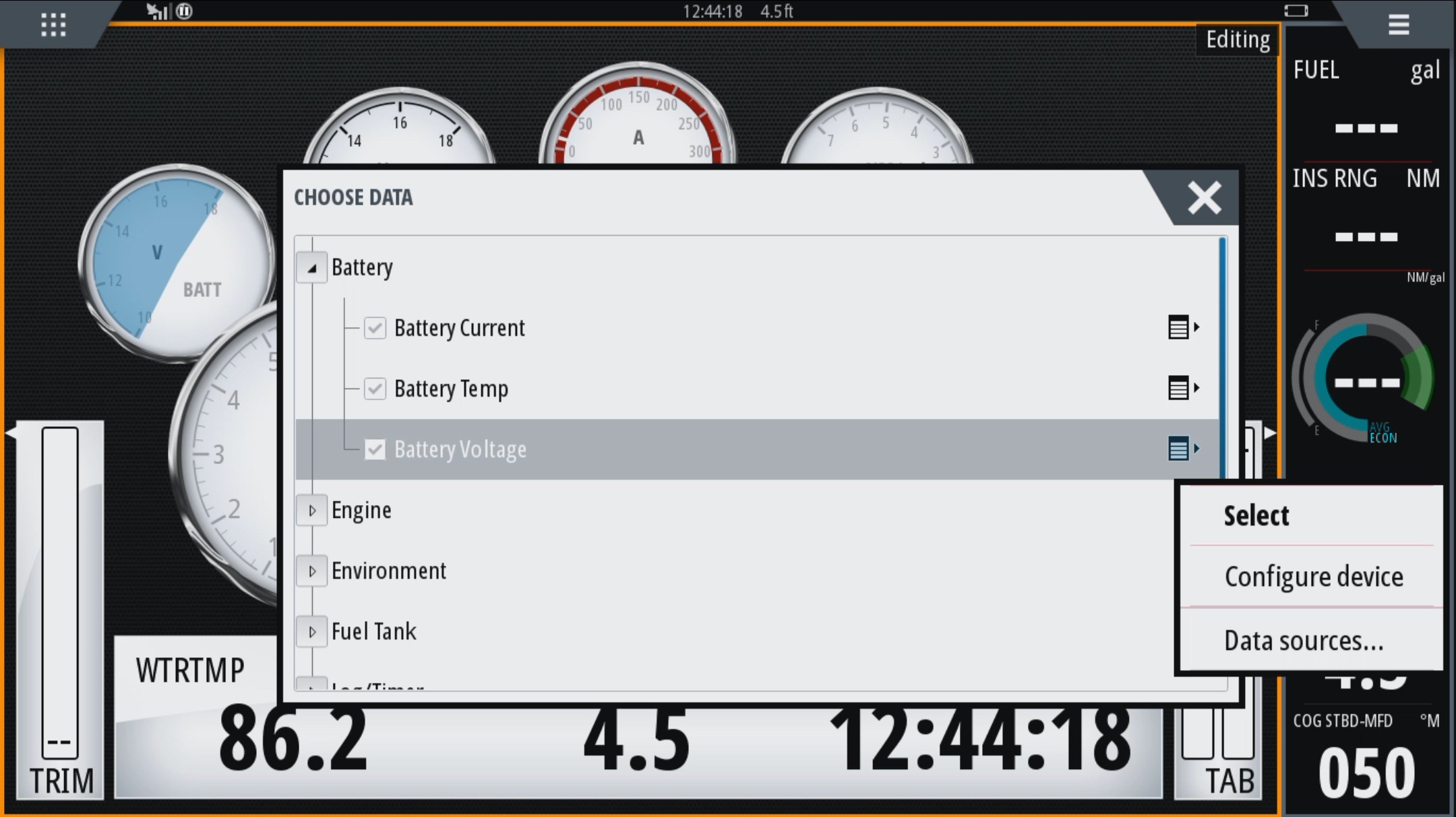

These screenshots show how you can program the NSS16 instrument panel with desired instruments, in this case using the “Data Sources” Select menu to choose between displaying alternator voltage with data instance 49 or the main battery bank voltage with instance 0. Note again that the OPE-Tether offers a lot more information via Wifi than via N2K, albeit not as conveniently.
I might add that I am still enamored with my Simarine Pico system, though it does not yet support NMEA 2000. I have a zillion shunts on the boat, and it provides me with realtime charging and currents coming from both alternators, and into all battery banks. It also gives me temp for the engine, engine and battery compartments, and much other useful information.


If you’re not already acquainted with Luis Soltero, I profiled his deep marine electronics industry and trawler/sail cruising career here:
https://panbo.com/team-soltero-starpilot-gmn-redport-bliss-so-much-more/
Luis recently retired as CTO of Global Marine Networks, and isn’t it wonderful that now he’s sharing his latest marine technology passion and expertise on Panbo? How about a warm welcome from readers, and maybe he’ll share some more.
Steve Mitchell is also using the WS500 and reviewed it here:
https://seabits.com/wakespeed-ws-500-regulator-review/
Thanks Ben! I absolutely love my WS-500s – they have allowed me to stop worrying about charging while underway, and at how much power I use at anchor. The biggest challenge with them was configuring them, and there was little to no remote monitoring. Excited to see Luis’ OPE Tether solves both of those issues!
I liked this post very much, as I have a similar issue. We have 2 engines, equipped with 24V/120A each. 25 years ago (!) we updated the regulators to Mastervolt’s AlphaPro regulators, charging a 800Ah flooded battery.
It took some time to optimal adjust these regulators, the battery needs to be charged full, before you can setup the regulators.
Anyway, they are not connected with the (Victron) BMS.
Searching for a solution, I found a reference to the WS500 on a Victron Users Forum.
Alternative to the WS500 is also Mastervolts system, as I learned lately. The newer AlphaPro III connect via Masterbus to the MasterShunt. The Mastershunt supplies the AlphaPro III with battery status, including temperature. The temperature of the alternators are also monitored. Everything fully adjustable, if you know what you are doing.
Summary, if you have already a Mastervolt system, this can be a nice alternative. Masterbus has also a certified NMEA2000 bridge, to connect to the rest of your system. Or integrates into CZONE, which in turn is suported by most brands MFD.
Go on with your good work, I learned a lot from your blogs and articles.
Yup the WS500 is a breakthrough in charging management. Rick at Offroad software solutions also has written some config software for the WS500, and it works perfectly.
https://offgridsoftwaresolutions.com/product-category/software/
Thank you for the great detailed write up. I appreciate the effort that went into it.
For the ones who want to see the history of this device, by coincedence I found this:
http://arduinoalternatorregulator.blogspot.com/
WS500 was called previously the “VSR Alternator Regulator”.
We are both a Wakespeed & a Balmar dealer and the WS500 regulator is simply amazing but for a “voltage regulator” the MC-614 is one of the most configurable there is. Where the MC-614 may not work the WS500 will.
For anyone in a similar situation, a resistor & toggle switch on the battery temp circuit of the Balmar MC-614 (there are two temp ports on an MC-614) can also be used to do a forced float.
I don’t remember the values off the top of my head, and it would vary based on your voltage set points. We have done this before and it works beautifully. It just tricks the regulator into thinking the batteries are hot and the voltage is reduced to a float level. A rotary variable resistor can be used to figure out the actual resistor you’ll need.
Thank you for the excellent feature highlighting our Wakespeed WS500 Alternator Regulator. Mr. Soltero’s description of the issues that led him to Wakespeed, encapsulates the challenge with external multi-stage voltage regulators. During my 15 years at Balmar, I’ve heard similar stories time and again.
While using charging voltage and field percentage to determine battery condition may work well in the lab, charge control limited to those criteria has proven to be far less than ideal in “real world” conditions. As Mr. Soltero notes in his article, traditional voltage regulation leaves much to be desired when large transient loads are present and multiple sources are competing to deliver charging current to the batteries — the addition of current monitoring and connection to other system components via CANbus communication is an absolute game changer when it comes to intelligent charge control.
The genesis of the Wakespeed WS500 actually started nearly eight years ago as a result of circumstances very similar to those Mr. Soltero describes in the article. As Mr. Jensen notes in his comments on the article, the WS500 was first designed by my partner, Al Thomason, as a response to persistent charging challenges he experienced on his own vessel while using popular multi-stage voltage regulators. The WS500 is actually the 4th generation of Al’s original VSR alternator regulator design, which he shared with a community of world cruisers on his blog. This design has seen thousands of ocean miles in its various stages of development, and has proven to be the center of a well proven charging platform. We’re proud to offer a high quality, American-made product that delivers a better charging experience.
Wakespeed continues to be a strong advocate for an open environment, where others can build upon the concepts that the WS500 represents. We’re really enthusiastic about new compatible technologies like the OPE Tether, which adds even greater functionality and reach to the regulator. We believe that a community of effort is much a much healthier approach to innovation than the traditional proprietary dead end. We’re pleased to see that OPE’s Tether, Offgrid Software’s WS500 configuration and monitoring application, and our own Configuration Software Utility, available at http://www.wakespeed.com, and our simple, onboard DIP switch controls provide a wealth of tools to make the WS500 the most advanced, configurable and universal alternator charge controller on the market — and you don’t need to chase down a magnetic screwdriver to make it work.
Thanks, again, for a terrific article.
Rick Jones
Wakespeed
Panbo is wonderful, and the two Bens write wonderful articles, but Luis, this is one of the best articles IMHO on Panbo in a while. The WS500 seems like a game changer.
But here is the thing, as a consumer, at least to me, the WS500 seems like a perfect companion to the Balmar SG200. Clearly reading between the lines there is some history between the Balmar folks and the Wakespeed folks. But as I read this I think of the SG200, this super advanced shunt that can accurately monitor batteries state over their life, and share that info over a CANBUS to displays and a Bluetooth network. Then we have the WS500 that can properly control single Alternators (or multiple Alternators by using multiple WS500 over a J1939 CANBUS) but requires a shunt and doesn’t really have much of a display. Then you add the OPE tether into the mix that adds GUI program-ability and wifi access. ….. So imagine if all those worked together. Imagine if the WS500 could easily integrate into a SG200 by simply pluging into the CANBUS. The WS500 could simplify its wiring harness now (using the SG200 shunt measurements). The WS500 now could vary its output based on state of health of the batteries. I could easily see the status of charging on the SG200 displays and phone via bluetooth.
Maybe I am crazy, but with an SG200 system, one or two WS500s, one or two high output alternators (Balmar, Mastervolt, etc.), and lithium batteries (Relion, BattleBorn, etc.) … a boater could basically create a 12volt or 24volt generator replacement system very similar to the Nigel Calder Triskel Marine Integrel Solution that is only designed for 48volts at a potentially cheaper or similar price. (3, 4, or even 5+ kW of power)
I had heard a rumor (a year ago) that Balmar had wanted to design a regulator that works with the SG200.
Just a thought, but maybe Rick Jones, Chris Witzgall, and others get together and revolutionize the Boat, RV, and even Off-Grid DC power market. That is just my $0.02.
Thanks, Matthew, Luis has definitely hit upon a good number of key points with his review. The ability to access accurate information about battery health is an essential aspect of proper regulation, so, I certainly understand your interest in a pairing between products.
We’re actually already doing one better. One of the most important parts of the WS500’s functionality is the ability to communicate directly with a growing number of BMS products, including the REC-BMS, Lithionics Batteries’ Never-Die BMS, and the MG Master BMS from MG Energy via CANbus connection. Getting information regarding SOC, loads, and battery temperature directly from the BMS is certainly the most accurate option, rather than relying on a monitor for second hand information — and the side benefit of simplifying system wiring is certainly an added bonus. In addition, communicating with the BMS directly give us the distinct advantage of knowing when the battery is going to disconnect — kind of a critical feature. That being said, we’ve heard great things about the SG200, and we commend Balmar on what appears to be a terrific product.
One of the exciting aspects of the WS500 is its ability to learn CANbus languages and libraries, which means that we can support a broad community of products and brands — so we’re not limited to a proprietary system. While the WS500 depends largely on the RV-C command language, we’re also able to participate in other systems that use RV-C, OSEnergy, SMA or a number of other popular command libraries. In terms of monitoring, chances are you’ll start seeing a number of products by various manufacturers who will have the ability to interface with the WS500 via CANbus. A number of integrations have already been proven in the field. Certainly true of the battery industry as well. Several manufacturers have already announced new CAN-enabled products this year, and there are definitely more to come. We’ve got some exciting new stuff on the way, as well. Stay tuned!
Well, I guess it’s time for my 2-bits. As a somewhat knowledgeable boater, and owner of a somewhat complicated large powerboat (’78-vintage Tollycraft 48), I read the above-posted article, and associated responses with considerable dismay.
SERIOUSLY? Do us poor schmucks that simply want to operate our boats safely and correctly, and equip our boats accordingly, REALLY need to deal with CANbus, open environments, so-and-so’s software, somebody else’s precision shunt, etc. simply to install a charging system to go boating???? Must we find a trusted local marine electrician, that is now not only ABYC-certified, but also board-certified in (COBOL, Dos, Java, C++, name your software flavor-du-jour), and also conversant in connectivity to all manner of display and/or control GUIs via Bluetooth, for gosh sakes?
Sorry to rant here, but to all who are enamored of such technology, please remember that the vast majority of boaters may not be so inclined, nor technically equipped to do so. And I, for one, am feeling punked at the moment, and am discouraged by this “look what I can do with a single line of code” mentality, to the detriment of those that believe in the eons-old maritime notion that Keep It Simple is good, and sometimes less is more.
And sorry Rod, a manual “force to float” to make the Balmar 614 behave is technically a correct solution, but simply wrong for the 99.9% of the boat owners that I know, and certainly me. Balmar should be ashamed.
Regards,
Pete
Geez, Pete, sorry for your distress but I think you missed a lot of nuance in this entry. Like:
“For most users, that is pretty much it. Connect the ignition, alternator power, voltage sense, and battery shunt current sensing wires. Hook up the alternator and battery temperature sensors. Finally, configure the switches for battery chemistry and Amp/Hr capacity, and off you go to worry-free battery charging nirvana.”
In other words, the Wakespeed WS500 can be a fairly simple install in many cases, and that’s certainly true for the many marine electric power specialists that install such gear for boaters who have no interest in doing it themselves. In fact, the OPE-Tether portion of the article is also about how specialists can now troubleshoot and manage systems like this from afar, even better for boaters who want to keep their boat time simple.
Meanwhile, the author’s boat Bliss has a notably unusual power setup — though it might get more common, given how much electricity is getting created efficiently — and thus required a more complex setup. And while I can tell you that a lot of readers are grateful for how deeply Luis explained it, the detail was never meant for every boater.
PS To my knowledge, Balmar has never promoted the “force to float” option as a feature (and I’ve spent a fair amount of time puzzling over their smart regulator manual). So I think it’s an expert feature that doesn’t even get mentioned unless there’s an appropriate need, and therefor trying to shame them about it as if they’re trying to “sell” it to all boaters is itself shameful.
We’re living in hard times, mate, and a lot of people are getting angry about a lot of things. I’m not seeing how that helps.
I for one enjoyed this article, but I also enjoyed this reply. I didn’t see it as angry, but more an expression of the frustration many are feeling (myself included) by the lack of common sense that is prevailing today at the intersection of geekdom and boating. I also share the frustration with Balmar, a company I like and whose products I use, because I have come to realize that their regulators are not as smart out of the box as we’d hoped, as evidenced by the credible articles over at Morganscloud.com that address the problems with default regulator configurations leading to premature battery failure. The problem is there are a million possible configurations out there and wide gaps in peoples’ capabilities so I understand how a company like Balmar can’t hold everybody’s hands and consult from afar. But their silence on this front is a little deafening and the rather stagnant innovation in their product line has me wondering if they are on the forefront of their space. Given this, I have chosen to keep things simple — absolutely no lithium ion tech or anything even close to experimental (I have a 420 Ahr 12v Lifeline AGM bank and a single AGM spiral battery for the starter bank. My balmar 100A alternator, driven by my yanmar 3qm30, is regulated by a balmar mc614 to the house bank with a balmar duo charger from there to the starter bank). I know that I can do more to customize my charging curves and work out an equalization regimen that would extend battery life, but I have more studying to do before I’m sure I know what the h*ll I’m doing — don’t want to cause more harm than good. For the time being, I know I may be shortening battery life, but in this space, the cost and ease of replacing the batteries is not as onerous as being a guinea pig with new tech. It is too bad in this litigious world that companies have to take an arm’s length approach with customers. I’d love it if the Balmar site went farther and deeper into exploring these topics of how to optimize our charging systems. Ideally, companies such as Balmar could do a better job of advocating optimized charging architectures for varying scenarios. Right now, this space feels more like building a PC with off-the-shelf components of varying quality as compared to buying a Mac that has the system design burden taken care of from the outset.
Brian, you bring up some great points. While the article does tend toward some techie-friendly aspects of the Wakespeed WS500, we’ve been working to create multiple pathways to provide a user interface that’s as simple or as complex as the user chooses to make it. While we love the idea of access from a smartphone, we’re also able to make it as simple to configure the WS500 as flipping a few DIP switches to match the regulator to the batteries.
Even easier, we’ve provided close to thirty pre-engineered configurations for battery technologies and battery brands which can be downloaded from the Wakespeed website, and can be uploaded to the regulator with a basic Windows computer and a micro USB cable. The process takes just a few minutes, and can be done right at the desk or work table. These configuration profiles take into consideration target voltages, minimum and maximum amps, alternator temperatures and many other factors specific to manufacturers’ recommendations. We agree that there are myriad factors in tailoring charging to the many battery brands and technologies out there, and we think that this approach does much of the legwork that makes advanced programming a dreaded chore. We’ve got an excellent lifeline battery program available on the website that was developed with the assistance of the team at Lifeline Batteries.
Hi Peter,
the nice thing about the ws500 is that not only does it allow gear heads (like me) full control over the charging cycle, but also allows more utilitarian users the ability to easily install a system that will efficiently care for their battery bank. With the regulator users will never have to worry about over charging their batteries no matter what loads or alternative energy producers they may have. And batteries will be charged at their maximum efficiency reducing engine run times.
The harness that comes with the regulator has wires for
1. Battery voltage sense lines
2. power and ground leads
3. field wire
4. battery temp probe
5. alternator temp probe
and
6. sense wires that go to a shunt.
So basically the same connections as many “smart” regulators with the addition of 2 leads for the shunt sense wires. The WS500 is no more complicated to wire up than say a Balmar or other regulator.
If you install a common ($20-$40 500Amp/50mv such as https://www.ebay.com/i/143507591547?chn=ps ) shunt with some form of lead acid battery then absolutely no programming is required. After connecting the wires you use dip switches to select the battery type (Wed, AGM, Gel, Carbon Foam) and the battery bank capacity. That is all there is to it.
Most boats already have battery shunts installed since they are used by State-of-Charge battery monitoring systems. Chances are that you have one already (i did). If you do have one then you can piggy back of it. If its not a 500/50 and you don’t want to program the regulator then you can purchase a shut, like the one above, and put in series with the current shunt.
My recommendation is that if you are having charging issues then you might look at the WS500. The fact that it does use a shunt allows the regulator to precisely determine the state of charge of your battery bank while it moves through its charge cycle. Very few regulators currently on the market allow this level precision during charging.
Bottom line… even for fairly complex installs there is no need for programming of the ws500. Most users will be able to easily install and configure the unit for their needs.
Users moving into more the complex Lithium battery systems will need better control over the charging cycle and hence the need for the CAN bus. Communication between the regulator and the Battery Monitoring System is essential to keep things safe if/when the battery bank shuts off. Under these conditions the alternator must immediately disconnect to prevent damage, CAN communication between the WS500 and many popular BMS’ increases safety and reliability of these systems. I will discuss this and more about battery systems and their care in a future article coming soon..
Take care.
–luis
Hi Luis,
Thanks for your comments, and for your posting of your original article. And now, with my tongue firmly in cheek, I say “NOW you tell me!” Had your article been posted six months earlier, I might well be on your path as well.
At least the FIRST part of your path! I recognize that the WS500 may well be a regulator that accomplishes 100% of what I (and I believe to be the 99.9% of the rest of the boating crowd) needs in a regulator, simply with the setting of the dip switches. Bit of a pricey solution, but perhaps the cost of doing business these days. But I suggest, not a simple solution, by any means.
Unless I have my head buried in the sand, I believe the WS500 is a relatively new arrival on the regulator scene (at least for us consumer-level folks.) And thus not yet extensively wrung out by trusted experts. Yours is the first consumer review of the product that I’ve been able to find, and for that, I thank you again. I anxiously await further review and comment on the WS500, and may well go down that road in the future.
Regards,
Pete
Hi Pete, Rick from Wakespeed here. I definitely appreciate your addition to the conversation. While the WS500 does offer some really whiz bang features, it’s original design was my partner Al’s response to the inability of his engine-based charging system to take care of a large, traditional thick-plate flooded battery bank in his sixties-vintage Monk trawler. Certainly not high tech — but, as a live aboard, his system was required to support day-to-day loads that his popular, brand-name voltage regulator couldn’t handle. As Mr. Jansen noted above, earlier generations of the WS500 design have been available, and have been embraced by a dedicated group of world cruisers for more than six years and tens of thousands of ocean miles, The design has been refined to address newer battery technologies, but, at its heart, it was engineered from the start to address simple, real-world charging issues. As Luis and Ben have both noted, for most users, configuration is simple as setting a few DIP switches, or downloading a more targeted profile from the Wakespeed website.
Hi Ben,
No, I did indeed capture all of the nuances in the initial article. For brevity, I failed to post my backstory, which consists of many months and many thousands of dollars trying to modernize the electrical system of an old boat, and using largely Balmar hardware accordingly. Unfortunately for me, I completed that upgrade before I became aware of the WS500. My bad, perhaps.
But my prior work did, indeed, uncover (at least to me) what I consider a flaw in not only the 614’s technology, but certainly in their documentation. BALMAR does NOT capture a scenario while using the 614’s when programmed to properly prevent “premature floatation”. And that scenario is when so programmed, the regulators fail to recognize a 100% SOC on a cruise departing from shore power, with presumably fully-charged batteries. This condition may barbeque the battery(s) on that leg by not forcing the alternators to fall to float immediately. Yup, they’re the finest VOLTAGE regulators on the market. But isn’t that only part of what the consumer really needs?
Yes, the Wakespeed product appears to be a better solution. And perhaps some of my “anger” should be directed inward for making poor choices of hardware in the first place. Sorry if it comes across that way. Honest, I’m simply trying to promote collegial discussions, which should welcome discourse. Again, I apologize if I came across as too strident.
But I do believe Balmar deserves some kind of a ding for providing a product that appears to require a neanderthal manual method of “forcing to float” the alternators on leg one of a cruise, and certainly when that methodology is not acknowledged or discussed in their documentation. This “unadvertised (expert????) feature” of the 614’s really isn’t a feature-it’s a flaw, and deserves to be called out as such.
And lastly, I apologize for taking this conversation off-topic from the Wakespeed WS500. I’m anxious for this product to be extensively reviewed and evaluated by industry experts, and am hopeful that Wakespeed prospers accordingly. And I’m equally hopeful that those of us that simply want to go boating safely and comfortably without a PhD in Computer Science can do so.
Regards,
Pete
Correct, Pete, this article is not about the shortcomings of Balmar regulators in certain conditions, and as the guy who edited it, I’d like to keep it that way. There appear to be many ways to “barbecue” boat batteries, pretty much regardless of charging equipment used. That’s why complex expertise either has to be learned or purchased, at least given the current state of affairs. Que será, será.
Hi all, Luis now has a lot of WS500 info on his NMEA 2000 network, and he explains different ways to do it in a new section above:
https://panbo.com/how-wakespeeds-ws500-alternator-regulator-solves-complex-charging-issues-a-new-approach/#WS500toNMEA2000
Really interesting product. Two questions that maybe should be obvious but I can’t figure out:
1) Do I understand it correctly that the WS500 will measure the charging amps at the shunt coming into the batteries from all sources (including solar) and can be set to reduce the alternator charging amps if the total amps would otherwise exceed the maximum for the battery bank?
2) In a two engine installation, will the interconnected WS500s keep the tachometer on Yanmar engines (that is driven by the alternator) from sometimes going to 0 rpm when the batteries go into float?
Hello Carl,
To answer your questions…
1) yes. The house battery bank amp shunt on the negative return is used by the ws500 to monitor current going into the battery. It uses this current to move through its charging stages. Solar panels and other external charge sources do not affect it. Typically for most lead-acid batteries you would program the ws500 to move from acceptance to float when 3-4% in amps of the battery capacity in amp/hr is reached. For a 500 amp battery bank this would be 500*.03 or 15 amps. For this battery the ws500 would go from acceptance to float when 15 amps or less were seen on the shunt no matter who produced the current. For a lifeline AGM the ws500 would hold a constant voltage of 14.3 amps until a current of .5% of the batter capacity was seen. What is really nice is is that you can tune and customize the charge profile to suite you batteries and your specific charging requirements.
2) you would use 2 ws500s connected via an ethernet cable for a 2 engine application. The ws500 negotiate for a master and the master sets the charging targets. Both regulators work in cooridnation to meet these goals.
The current version of the firmware allows setting a TACHOMETER MIN FIELD. When set, MIN TACH, prevents the field from being totally turned off. This prevents the field from totally being turned off causing a loss of stator. I quote from the manual…
Tach Min Field: This is the % value the PWM will be kept at as the minimum drive when the DIP switch has selected TACH MODE. BE VERY CAREFUL with this value as it will set the floor in which the alternator is driven. If that floor is too high, it will prevent the regulator from ‘regulating’, burning out the battery. This is the actual PWM value sent to the field drive; though it is capped at 30% the full hardware PWM.
Note that newer version of the firmware will handle this more gracefully allowing the stator to continue working without worry about inadvertently affecting regulation. But this has not been released yet.
The tach min field is set for each regulator so you can run the engines at different RPMS and still have this work. The alternators could be mismatched (i.e. one large and one small) and the two regulators would still be able to make them work in a cohesive manner.
–luis
Hi Louis. Thanks for the reply. On my first question I have a slightly different concern. It”s a bit odd but in this day of large lithium battery banks and large solar arrays I bet I’m not alone. My lithium battery bank will be cabled and fused for 400 amps (12v). I intend to have two Balmar XT 170’s plus 1800 watts of solar. On a sunny day these together could go above 400 amps. I could derate the alternators to stay below the 400 amps but that wouldn’t be great on a cloudy day or at night. It would be wonderful if I could set the Wakespeed so it would automatically reduce the alternator charge amps to limit the total amps going into the bank to below 400.
Carl,
Your situation is not that odd; increasingly we see system installs with multiple charging source with many of them able to supply significant amounts of power. And as you pointed out, the sum of them can at time exceed the capacity of the battery system. There are two considerations here:
1) Max C rate of the battery.
2) Maximum system power capability
You did not mention the size of your Lithium battery bank, but if its C rate limit is below the 400A fuse size there is nothing more you need to do other than a standard WS500 install and configuration. By monitoring battery current the WS500 will adjust alternator output to assure the C rate is not exceeded, even if a portion of those amps being delivered comes from Solar or AC power chargers. So, let’s say you have 1,000Ah of battery and the manufacture has specified a continues charge C rate of 0.3C — the WS500 would limit battery current to 300A max, will within the operational range of your 400A fuse. And will not matter if all 300A comes from the alternators, or a mix of alternator + solar + Generator. As long as there is still headroom to manage the alternators, the WS500 will adjust alt output so the total system current to the battery is around the 300A limit.
However, let’s say you have 2,000Ah of battery, so the calculated current limit based on a 0.3C rate is now 600 amps, a bit too much for that fuse! In this case the approach Luis suggested would be one solution: In addition to defining limits the Battery wants to see (aka, C rate), also define an upper limit for the entire System: Perhaps set the System Watts Limit to 5,000W, that would cause the WS500 to cap delivered power to around 350-375A (depending on battery voltage).
Another approach would be to reduce the defined battery C rate from 0.3C to 0.18C (2,000Ah @ 0.18C 360A max). Adjusting the C rate down might be a simpler and more consistent approach as the resulting amperage limit will be independent of battery voltage.
With high energy systems becoming more common the need to properly engineer them also becomes critical. It is good that you have seen the need and hope this gives some additional insight on how the WS500 can help solve your situation.
Hello Carl,
To do what you want you would need to set SystemWattsCap under using the CPA command. This would limit the total power being fed into the batteries no matter who generates the current. Here is the excerpt from the WS500 manual that describes the feature.
System Watts Cap: This regulator will limit the system wattage to this value. Its primary use is to protect the driving engine and/or belts – by limiting the maximum amount of Work the engine is asked to do in behalf of the alternator. (Work being a function of BOTH Volts and Amps, hence Watts). It may also be used to limit the total amount of power being delivered into the battery by all charging sources. There is no derating or adjustment made to this value based on system voltage or selection of system battery size. System Watts Capacity is used to after applying the ‘Alt Derate xxx’ factors. It is used to protect the alternator from over current usage. A special feature is enabled by setting this = -1, the regulator will drive the alternator as hard as it can for a short period of time when 1st entering Bulk phase. This will then be used to define the Amp Limit of the Alternator.
Given the complexity of your setup you might call wakespeed or oceanplanet for advice on setup and configuration of the ws500 to best fit your needs.
Take care.
–luis
Carl (and others):
How to keep the Tach from dropping out during the charge cycle. A classic PITA for boaters for many years! As Luis pointed out, the WS500 has some features for defining a minimum tach field drive to keep tachs alive, it does work, but requires tuning for each vessel – and myself, I worry about such approaches as if not done carefully can result in a slight overcharge condition. Back with Lead-Acid batteries not that much of an issue, think of it as a mini-equalization step. But the Li based technology can be a problem..
As alluded to above, we do have something in Beta testing right now, an idea from one of our long time customers – a way to use the ‘Overcharge’ (aka, Finish) phase and have a more controlled transition between the end of the Acceptance phase and the Float phase – the classic critical tach dropout time.
In Beta testing now, contact us at [email protected] if you want to learn more.
Just a heads up for any one wanting to integrate the WS500 onto your NMEA backbone, the NBE100 route does not work.
Wakespeed has been purchased by Dragonfly Energy the the makers of Battleborne Li batteries. This is good for consumers for several reasons.
1. there is now a very large reputable company supporting and expanding the product
2. Features in the more expensive APS only version of the regulator (such as rpm based engine loading/whitespace discussed above) are now included in all wake speed products as of version 2.5.0.
–Luis
It’s been in the works for a while but as of latest Venus OS v2.90 update, the WS500 can be fully integrated into Victron’s power control and monitoring systems. And it looks great:
https://www.victronenergy.com/media/pg/Cerbo_GX/en/wakespeed-ws500-support.html
Meanwhile, my Balmar MC618 smart regulator with SmartLink monitoring and configuration is working quite nicely alongside Gizmo’s many Victron power products:
https://panbo.com/balmar-mc-618-regulator-with-smartlink-integration-first-look/
Hey Thanks for the write up. I particularly like you advanced wirings section, where did you find this info? I’m preping for my WS500 install but I’m finding the documentation underwhelming.
Thanks!
the place to look is in the programming manual. It’s quite technical but everything you need is there.
here is the link…
https://www.wakespeed.com/wp-content/uploads/Wakespeed-Communications-and-Configuration-Guide-v2.5.0-09.26.2022.pdf
Take care.
–Luis
Luis – many thanks for this post – I’m just getting to the point of wanting to play with my WS500 and this is a fantastic resource!
Luis, Rick, Ben, et al,
Would a WS500 integrate into a MasterVolt MLI 6000 application charged by twin Balmar alternators using a MasterVolt Multipurpose Contactor Output DC relay in the ignition wire on the WS500 to protect the alternators if a battery safety event were to occur abruptly?
And thereby get the inherent current monitoring benefit of the WS500 in my application?
Namely, could I ignore the WS500 CAN bus interface and just use the MLI Event Driven Commands to Suspend and Resume Charging via the relay thereby:
1) Reducing the likelihood of a battery safety event occurring.
2) If one did the WS500/alternators would already be shut down since Suspend Charging Commands precede battery disconnects?
Any special configuration programming required, or would it just be a DIP switch setting for the MV lithium?
Also, it was said the WS500 can support 2 alternators with its field current of 30A but how do you do that if there is only one field output wire?
I note that the Balmar MC-612-DUAL I am using now uses two alternator harnesses including two field wires, to the two alternators.
Finally, if Bruce Schwab is still reading this thread, can you tell me why you consider this single wire voltage regulator shut down design for battery safety events, to be only a secondary backup choice? What is the downside of it being the only protection?
Thanks people!
Eddie
Hi Eddie,
First the easy question: “how do you do that if there is only one field output wire?” use the same field wire going to both alternators. One field wire out of the alternator –> split –> one leg to each alternator. Basically as far as the Wakespeed is concerned you have one alternator with double the capacity of each of your blamers. I run 2 APS 250 amp alternators this way and have been doing so for about 3-4 years without issue. As long as the current draw from each alt is less than 7.5Amps you should be good… APS draws a max of 8 amps so just to be sure I throttle my Wakespeed to 90% of capacity… this also means the alts never run full out which is probably a good thing.
You could have 2 wakespeed regulators in master slave configuration (this is bruce’s preferred method) but that really complicates the install and adds expense. Note that the weak speed harness comes with one temp sensor for battery and one for alternator. With newer versions of the wakespeed firmware you can configure the battery sensor as a second alternator sensor. You will want to do this since your BMS protects the batteries and monitors temp. Alternately you could run the second alternator without a temp sensor which is what I do since I have lead batteries and need to monitor the battery temp during the charge cycle. If you want both alts temps monitored as well as the battery temp then you will need to two wakespeed regs.
BTW… wakespeed is totally cool with having 2 alts being driven by the single reg field wire.
Harder question: “Contactor Output DC relay in the ignition wire on the WS500 to protect the alternators…” simple answer
yes.
this method is very common especially with older LFP installs. It’s perfectly acceptable. The CAN bus control is much better since the BMS communicates its changing needs to the wakespeed… but cursing the field wire with a relay on a disconnect is perfectly acceptable. Having both methods is best which is Bruce’s point. And.. if the relay were to fail… well…
You still have the shunt on the batteries which the wakespeed can use for an acceptance phase. the acceptance phase is nice since it allows for cell rebalancing… having a direct voltage cutoff (which is what is used by many Li able regulators) does not allow for an acceptance period which could be detrimental to the batteries.
Finally, you can use the DIP settings but I would recommend programming the regulator with the specific charging details of your battery type and bank size.
–Luis
Eddie,
Hello! (DISCLAIMER: Al from Wakespeed)
Yes, you can connect up the WS500 in the way you describe. We call this a ‘Legacy’ install in that the WS500 does all the sensing directly as opposed to getting information via CAN. In doing so make sure to connect up all sensors:
– Battery Voltage
– Battery Current Shunt
– Battery Temperature
This will allow you to fully implement a custom Charge Profile for the install. Use the Wakespeed app, toggle on Expert Mode, and then adjust the individual CPx parameters — refer to the Wakespeed Configuration and Communications guide for details around each, and keep in mind: internally the WS500 thinks the Whole World only uses 12v/500Ah batteries — as such all the CPx values are defined against that. Example, declaring MaxBatAmps of 250 is how to set a 0.5C max charge rate (250/500 = 0.5) During Runtime voltage and battery size factors are applied to match the actual battery size and spec you are using.
Make sure to also look at the CPB: area for upper and lower temperature limits – is better to have the WS500 stop charging before the BMS does a physical disconnect – killing the whole boat. And take note of the Reduced Charge factors: This is another area the sensing of Bat Temp comes into play: It lets you defined a lower C rate to use as the battery approaches high/low temperature stress points.
Then there is the Charge Enable wire from the BMS: Here you have some options: Route to the Feature-in, configure the Feature-in to select Half-Power Mode and set the Half-Power derate value to 0% That will cause the WS500 to go into Standby mode when the BMS so signals. You can refer to the Victron VEbus BMS install guide and config we have on the Wakespeed website for an example of this usage.
Alternatively you can have that BMS wire disconnect the Brown Power Wire, or perhaps the Red ALT+ power wire.
Which brings me to a MAJOR CONSIDERATION: Does the MasterVolt BMS provide a 2 second or greater forewarning of a pending disconnect? And is that true for all disconnect events? (Major exception being direct short) Many BMS’s do not, instead they signal Stop-Charge at the same time as opening the contractor: This will result in a Load-Dump and likely cause significant damage. It is A CRITICAL POINT YOU WILL NEED TO CONFIRM in your system design. FYI, the aforementioned Victron VEbus BMS does not give this forewarning, and you will note that the output of the alternator bypasses the contractor as a mitigation. (Nope, not really ABCY complaint!) Please research this point carefully!
I will add, Wakespeed lists a number of battery/BMS that are ‘supported’ (Wakespeed app is likely the best place to look). Among the qualification processes we engineering-to-engineering and proof in the lab this critical safe handling of disconnect. Other solutions may well work, we just do not know — and it is up to the installer to assure a safe and well designed system.
Driving two same model Balmar Alternators on one engine with one WS500 is no issue, and it is often done. As Luis mentioned, just connect up the two fields in parallel. It is my preferred approach vs. twin WS500 on one engine. Though if the alternators are asymmetrical you will need individual WS500 for each. As to reliability, for vessels I do subscribe to carrying a redundant WS500: Preconfigured and all ready to go, in the Lightening Box — along with the handheld EPIRB, VHF, and Engine ECU module!
As to the benefit of CAN integration: perhaps the largest benefit, aside from simplified install, is while the WS500 is very good at battery level charge profile management, it has no visibility into the individual cells in the battery itself. This is where the BMS comes into play. Example, if towards the final state of charge an individual cell is a bit ahead of the rest, the BMS can signal to the WS500 to reduce charge current while it balances that cell, then after that, signal to resume charging at a higher rate. Same details around battery/cell temperature: The BMS can fully control the charge process based on the needs of the battery at a cell level. Now I will tell you, not all CAN connected BMS’s have that capability, but for the ones that do, it greatly improves the hand-in-hand system design of the WS500 and the BMS.
I hope this answers some of your questions, good luck! And let us know what you end up finding out with regards of the disconnect and forewarning.
Sorry for the late reply, but the answer when you’ve got Mastervolt Lithium batteries, or anyones batteries with a Mastershunt 500, is to get the Mastervolt AlphaPro.
Not only will it regulate like the Wakespeed, based on battery state of charge and current going into the battery, but with Lithium it will also prevent over charge events as the battery will send a “stop charging” event way before the battery disconnects from the bus due to overvoltage.
Luis,
Thanks for the quick response, sounds like you know your way around this stuff.
Couple more questions if you don’t mind:
MasterVolt says their MasterBus network I have now is CAN bus based, but l assume they overlaid it with their own proprietary data link protocol. I don’t know anything about CAN bus protocol, but I would assume it has the equivalent of the MV commands: Stop Charge, Battery Full, Voltage Low, Capacity Low, Battery Safety Event, etc.
I am curious why you say “The CAN bus control is much better since the BMS communicates its changing needs to the wakespeed”.
At the end of the day, the MV MLI lithium battery is doing the same thing, with their protocol, no? With the same net result of the turning the VR/alternators On and Off as needed to keep the battery in a safe operating envelope.
As regards the charging profile for the MV battery they want Vbulk = Vabsorption = 12.25V and Float = 3.5V so that will be what I am looking to set whatever VR I choose to. But I cannot find in the MV documentation how long you are supposed to hold the Absorption voltage for.
And I cannot find in the MV install manual what a Battery Full event is supposed to do. Do you think that this requires the alternators to suspend charging every time the battery decides its full? If so, suspending charging is not the same as Float.
More generally, I am confused by the roles of the VR vs the Battery in real time control of alternator charging. Sure, the VR needs to be set to the proper Bulk, Absorption, and Float values, but I see nothing in the MV MLI 6000 manual for when to go to Float. Any insight into that?
Battleborn talks about 20 mins to hold at Absorption, don’t see any info on Absorption time from MV. Makes it difficult to use a WS500 in an otherwise MV system.
If I read how the Absorption to Float transition decision is made using my MV shore charger, they simply say “when the battery is full it switches to Float”. No mention of the criteria for Full. So no help for setting up an alternator VR. The only way to process a “Battery Full” event would be to shut down the VR/alternator with the ignition relay as is done with Stop Charge commands, but no charging is not the same as Float, right?
So that leaves me with ignoring any Battery Full event and just rely on setting a WakeSpeed or Balmar VR’s Absorption timer to some fixed value. I could use the WS500 current meter and set a value there for the transition to Float, but MV does not specify that either.
I’d be asking MasterVolt tech support all this, but they no longer have phone support for their products.
Thanks again!
Eddie
Eddie,
Hello again! (DISCLAIMER: Al from Wakespeed).
Yes, Luis is a VERY knowledgeable chap, and a long time fellow traveling in the Wakespeed world. Will let him of course answer directly, but though would add a couple of highlights:
CAN: Yes, MasterVolt has CAN based system, but it is closed. They do not share the details with others, and at this point, it is unlikely we will add a MasterVolt CAN handler to the Wakespeed product (Note that we do have perhaps 20x special BMS CAN handlers in place for other BMS CAN protocols)
Battery Charging: With a Voltage Only regulator, the choice is to hold for a time period to decide when the battery is full. But that is not Best Practice. Without exception, the preferred charge process for batteries (from every manufactures I have seen), is to hold battery voltage and monitor battery current as it declined. Often called the Tail Current. When the battery acceptance current reaches typically 1-3% of battery capacity — that is the true indicator of a fully charged battery. Case in point: LifeLine AGM ask for 14.3v until the tail current reaches 0.6% of its battery capacity. (This BTW was the motivating factor for the development of the Wakespeed, to be able to monitor tail current to decide proper full battery charge)
When setting up a Charge Profile in the Wakespeed the CPA: command lets you set these parameters: Voltage and Tail current, and yes there is also a Timeout option – but that is more of a safety backstop, in case something goes sideways with the battery current monitoring.
I have no doubt Mastervolt uses a like approach withing their closed ecosystem. But not sure if they publish such details for 3rd party use.
-al-
Al,
Thanks for jumping in. Just saw your post after I sent the one to Luis.
I surmise MV MLI battery systems, when it comes to alternator charging, presume their batteries are connected via their own proprietary CAN bus (MasterBus) to their own MasterBus conformant alternators.
So, what I am trying to do with Balmar alternators indeed requires the legacy design using basically a MasterBus controlled ON/OFF switch in the VR ignition wire.
The WakeSpeed architecture seems to want to be a bigger piece of the BMS function in the system. Which cannot be supported given MV’s closed architecture. So, there is no real information available to the outside world for the WS500 to use on a CAN bus.
However, this does not mean MV does not have a robust BMS. I think their use of an external Blue Seas 500A RBS attests to that as well as their emphasis on heavy duty high charging and discharging applications.
I will indeed use the WS500 battery Voltage and Current Sensors, but external battery temperature sensors are specifically discouraged in the MLI installation manual. This is just as well because I know from experience that the VR used must have a temperature sensor for each alternator to keep them from overheating in the tropics with high engine compartment temperatures. The Balmar VR has worked without fail for over 10 years now in the existing TPPL AGM battery system that actually has lower impedance and can handle way more inrush current than lithium batteries can, in the operational state of charge application we have.
Again, if there are any internal battery temperature issues, cell imbalances, overcurrent, overvoltage, etc. it’s up to the MV internal BMS to signal to the VR/alternators to Suspend Charging.
I am trying to confirm a battery disconnect will always be preceded by a Stop Charge when alternator charging. From the manual “before the battery reaches the limits of the operating specifications, the Stop Charge event is triggered. When configured this event forces the MasterVolt charger to switch off and resume charging after 10 minutes. The settings depend on the used charger because different chargers have different state option. Check the manual of the used charger for to setting the charging state”.
I’ve got to believe that if they have this precaution for their MasterVolt SHORE charger, which should be incapable of a load dump (true?), then they warn their own alternators in a similar manner. And therefore, it is this Stop Charge before a Battery Disconnect event, I want to exploit for controlling the alternators.
The scenario then is: Stop Charge > MV DC relay opens VR ignition wire > Battery Disconnect > life is good.
Nevertheless, I’d like a MV apps engineer confirm this.
BTW the reason I am not using MV alternators is because they fall surprisingly short of Balmar’s current output at temperature and charging RPMs. As well as seem problematic in dual alternators-single engine configurations.
I am relying on the maximum output of the alternators to be well less than the maximum continuous charging rate of either of the two MLI batteries in the house bank (which is also the start bank). So, no need to redefine C rate on the fly due nominal temperature issues that I can see.
My “legacy” approach should allow either of the two batteries to suspend charging, then disconnect, and the vessel to carry on once the VR relay is reset by the crew – without having to kill the engine incidentally. That manual reset capability for the ignition relay via the MV monitoring panel I am still trying to confirm.
It does not sound like a Charge Enable wire from the BMS is available from the MLI, so no feature-in Standby capability. We’ll just kill the ignition wire as stated. Not sure that is much of a disadvantage.
As regards the WS500 charge profile management and its ability to receive a BMS command to reduce charging while cell balancing goes on, that is not an option since there is no CAN bus interface as such. The “BMS signal” will simply be Suspend Charge until the battery sorts it out.
Incidentally, I am having trouble finding in the MLI manual how charging is Resumed via a MLI signal (MasterBus data command).
As to whether or not a MasterVolt battery/BMS is “supported”, I did not see so in a quick look at your list. But it seems to me all that is required of the WS500 is to provide the Bulk = Absorption =14.25V and Float = 13.5V setting capability. And not go haywire as my relay switches your ignition wire on and off. Something the existing Balmar I have been told could do.
The real impetus for choosing a WS500 is the current sensing shunt that may help to ascertain when Absorption should terminate.
I have always been concerned about seeing how if shore power is toggled on and off at the dock for some reason while I know the batteries have just gone thru a long Bulk and Absorption process, that the Balmar VR will briefly go back to Bulk, but then spend another 4 hours in Absorption BBQing the batteries as said above. And sailing down the coast and switching the engine on and off depending on the availability of wind, also sends the batteries back to a long multi-hour Absorption battery BBQ as well when the engine is restarted.
That said, I need to recheck if I don’t just have a timer override on the % field current method of determining the end of Absorption.
Just for the record, I also need to get a statement out of Odyssey about how bad frequent, excessively long, and unnecessary Absorption times are for TPPL AGM batteries. They did last 10 years with my light usage routines of about 7 days per month for 10 years of on-the-ocean usage. Thats about to change once I am a LFP boat.
Hence the current shunt interest in the WS500 determining Absorption duration with more certainty. Hopefully. Sigh.
Comments? Corrections? Clarifications?
Very much appreciated,
Eddie
Eddie,
(DISCLAIMER: Al from Wakespeed)
While I can not comment on the specifics of your system without a relationship with the battery manufacture and an example in our lab for proofing, it does sound like you have a good handle on the key issues.
Some notes on your last post:
You are correct, Electronics Devices (inverter/chargers, MPPS, and the WS500 for that mater) will quickly detect a load-dump situation and shut things down. It is the Alternator itself that is the problem here! Due to the massive indicative nature of Alternators, without some place to dump that energy it will raise voltage in an attempt to ride itself of that energy. Curiously, I have seen some indication of this Inductive Kick on large (10KW+) inverter/chargers as well, but no where near the extent alternators are able to do.
Make sure the alternators have protective Avalanche Diodes. (SAE/ISO Best Practice for suppression of load-dumps)
Many Li battery companies discourage BTS as a way to assure Temperature Compensation is disabled. You can disable TempComp via the CPB command.
Really nail down that forewarning nature of the signal wire from the BMS!
Take care of all added parts, remember each additional components introduces a failure mode. We had an example of an Legacy Li install (Did not need to be BTW, as CAN support was available, the installer decided not to use it) where a small Bosch-type cube relay way in the charge disable signal path. That relay failed intermittently,and caused a catastrophic issue with the system. No one was hurt, but vessel needed to be towed in, and as the alternators had no Avalanche Diodes there was a lot of other damage. Failed $2.00 relay. These High Energy Systems are a different game!
And yes, the monitoring of Acceptance Tail Current is a key value to assure not only proper charging of batteries, but also prevent over-charging situations as you described. Key example, when we came into port for provisioning we would top off the water tanks and charge the batteries with low-cost shore-power. We would also do a load of laundry while water was easily available. Often we would be ready to pull away from dock while the load was drying. In this case the batteries were full but to support the dryer the alternator produced perhaps a 100A. As the WS500 measured battery current it could tell the batteries were full and transition to float mode within a minute or so. Alternator was still working hard to power the dryer, but we were not cooking off the batteries by being held in Absorption phase!
Again sounds like you are getting a good handle on things. Best of luck!
-al-
I’ve had several people tell me that a DC-DC charger that’s float charging the start battery from the lithium bank will – in the event of a BMS shutdown – dissipate a surge from the alternator harmlessly into the start battery. Is this accurate?
Al,
Wow. $2 relay in a high output/high charge acceptance rate system. At 100 times more expensive the MV relay better not fail.
Seriously, this whole exercise has me at times asking myself if the lithium conversion is worth it. The TPPL AGM config is so much simpler and robust in nature.
I am totally sensitive to the additional failure modes implicit in a lithium system with the requisite additional BMS componentry and configuration coding found in a BMS.
We are going lithium because of weight and most importantly the promise of uniform high load power handling over a broader state of charge. Period. Everything else about it is a pain in the neck. That latter advantage had better be there or I will be extremely disappointed.
Given the morass of marketing claims and how they break down in specific applicaitions instances, I will believe the advantages when I can measure them.
Carl,
My guess is it would not be fast enough to handle a spike the way others have measured them. Maybe someone will comment.
I will be keeping a small TPPL AGM 100Ah as a Reserve Bank to quickly and easily turn the boat back into a continuously operable lead acid design in case the whole boat suddenly goes dark. I will be using a MasterVolt Mac Plus DC-DC converter as well. My DC-DC question is what it will do if the input side abruptly has its battery disconnected and is left floating. Anybody know the answer to that one?
Thx
Eddie
Nice article, I’ve been enjoying my WS500 for the past 2 years. I recently connected my WS500 to my N2K network as I’d like to get data on the alternator (alternator temperature, charge state, field %, etc) to display on my MFD. I’ve made up a rj45 wire to n2k cable and can see the ws500 on my network but am not seeing the alternator data in any of the PGN’s. What PGN will give me full status of the alternator data? I can see the battery stats from the WS500 but I already had these from my Victron battery monitor. Thanks
The Alternator data shows up as a battery using PGN 127506 and 127508. If my memory serves me the ID is 49 so battery is 0 and alternator is 49. The programming manual for the WS500 found at wakespeed.com has a discussion about this. Note that I can select the battery ID to display on my Simrad displays but not on my Raymarine i70. The i70 only displays data for battery with ID 0.
Luis, thanks very much. I was able to get my alternator temp by using battery ID 49 and 50 (have two wakespeed) and charge mode status. I wasn’t able to find alternator field % but am not sure if this is part of any PGN. Do you know if this data is available?
You might take a look at PGN
//*****************************************************************************
// Engine parameters dynamic — 127489
// Rx:
// – EngineInstance Engine instance.
// – EngineOilPress in Pascal
// – EngineOilTemp in Kelvin
// – EngineCoolantTemp in Kelvin
// – AltenatorVoltage in Voltage
// – FuelRate in litres/hour
// – EngineHours in seconds
// – EngineCoolantPress in Pascal
// – EngineFuelPress in Pascal
// – EngineLoad in % (Receive only)
// – EngineTorque in %
According to canboat
https://github.com/canboat/canboat/blob/master/analyzer/pgn.h
this PGN should contain …
VOLTAGE_I16_10MV_FIELD(“Alternator Potential”),
Not sure if wakespeed provides that.. but this is the only N2K PGN that could have the Field potential.
Alternator In volgate in the Wakespeed docs looks like it might have what you are looking for.
Hello.
(Disclaimer, Al from Wakespeed).
You can get the field drive % from PGN 127510, the field called: PERCENTAGE_U8_FIELD(“Charge Current Limit”)
Hope this helps! (And Thank you Luis for chiming in!)
Al, thanks, unfortunately I’ve confirmed the Maretron N2Kview software can’t currently display that PGN. Maybe it will be added to a future update.
For those with you with wakespeed regulators on your vessels, I would like to announce that the Wakespeed management software that was originally included with the OPE tether has been incorporated into the PredictWind DataHub (DH) with release V4.22. The software supports both the original WS500 and the new WS500pro regulators.
For those not familiar with the OPE Tether, the software was designed to provide real time monitoring and configuration of the wakespeed products over the RV-C/NMEA2000 CAN bus. This allows monitoring and programing the regulators without having to open the case to access the USB port on the device. The wakespeed regulators are accessed through a mobile friendly web ui which allows monitoring and programming from anywhere on the vessel.
The software also can be used to update the firmware on the regulators and comes embedded with the latest wakespeed version 2.6.0 for both the standard and pro versions. Currently, wakespeed firmware updates must be done through a USB connection between the DH and the regulators although future versions will support firmware updates over CAN (for the WS500pro only).
Although a bit dated now, the following article describes an early version of the software as well as a review of the wakespeed WS500.
https://panbo.com/how-wakespeeds-ws500-alternator-regulator-solves-complex-charging-issues-a-new-approach/
To enable the wakespeed subsystem on the PredictWind DataHub(DH) do the following after connecting the regulator to your NMEA2000/CAN network.
1. Update the DH to version 4.22 using the standard software update methods
2. Login to the DH as the superadmin user (with default password superadmin) and then navigate to Services->NMEA->Settings->Advanced and push the “Enable WS500” button.
3. you will see a new menu item called Wakespeed AP/WS500 appear under the services menu.
4. Navigate to Services->Wakespeed AP/WS500 and check the enable box and hit save and apply.
5. Select the desired regulator under “Regulator Interface” and hit save & apply.
For those of you with OPE Tethers… Note that OPE has discontinued the product. I can modify the software on the OPE Tether to convert them into PredictWind DataHubs if you like. This requires enabling a remote session and providing me with your access URLs. I can then login remotely into your system to convert the unit into a DH. Once done the hardware will support the full DH feature set.
As for support…
The PredictWind support staff knows little to nothing about the wakespeed regulators but can provide support for anything else related to DH’s functionality. So please do not reach out to them with questions about the wakespeed since they will be able to provide little to no insight.
Reach out to me for defects/bugs in the software.
For wakespeed programming, configuration advice, use of the DH wakespeed app, etc… you can contact OPE at http://www.oceanplanetenergy.com. OPE can provide support for anything related to the wakespeed regs and the wakespeed app on the DH. OPE can not provide general support on DH itself. Only the wakespeed app. Note that service fees may apply if you are not currently an OPE customer.
for those of you on the west coast, Jordan at acrossoceansystems.com can also provide wakespeed regulator assistance with DH.
Here is a link to the DH product page and support center
https://www.predictwind.com/datahub
https://help.predictwind.com/en/collections/3389802-datahub
OPE Tether manual
https://docs.google.com/document/d/1k8IvLPfbOc1jEinVBlL1SA08ng9FoSjvTANK9M3PZLg/edit?tab=t.0#heading=h.ie3pp8dtjkk7
Wakespeed programming documentation
https://www.wakespeed.com/wp-content/uploads/Wakespeed-Communications-and-Configuration-Guide-v2.6.0.pdf
Take care,
–luis