
Garmin Radar & Maretron Compass, puzzles!
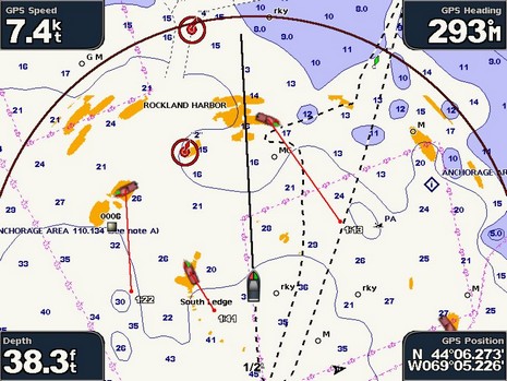
Last week I got another brief look at Slancha’s Garmin 18” HD radar in action, only this time I got this screen shot showing its MARPA abilities in action, bigger here . But I’m still a bit puzzled about the implementation, and, as noted in the earlier entry on this unit, can’t find a thing about it in the manual. My guess is that the projected point and time represent the calculated CPA relative to your boat, not relative to the chart. Let’s consider the top right target first, and note that the arc represents where Slancha could be in 3 minutes at this speed. CPA, of course, is figured on the current speed and heading of your boat and the target. So I think that the Garmin is telling us that in 1 minute and 13 seconds the target will be a close as it’s going to and it will be broad on the starboard bow (but when this takes place we’ll be nearing that next bathy line and the target will be near that 11’ bump).
In other words the target’s vector represents its relative motion to our boat, not its true track across the chart. By that analysis, the target upper left is probably stopped or moored, and thus its relative motion straight down the chart and its CPA in 1:22 when it will be right on our port beam (and still in the same spot on the chart). Are you with me? And can you figure out what the third target at South Ledge is up to (aside from a likely mistaken heading or CPA calculation? Garmin, by the way, put up a major (Ver 4.1) update to 3–, 4–, and 5000 series MFDs last week. The 4– and 500 series got a 4.0 update a couple weeks ago—with many similar improvements—and BluewaterPirate already made videos illustrating them.
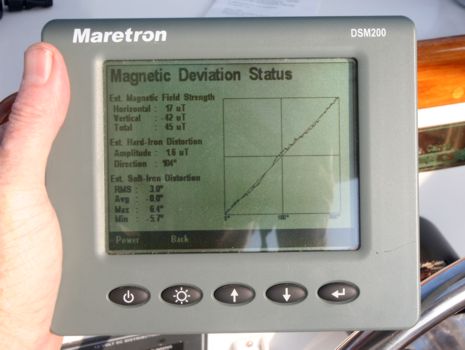
My real reason for being on Slancha is embarrassing. The first time I installed the Maretron N2K compass that made the MARPA possible, there was a bucket containing two serious cordless tools directly beneath it. The next time out—without the bucket—Slancha’s radar overlay was about 15 degrees off on many headings! So again I did a 30 second install of the DSM200 below, and again we went through its slick guided deviation compensation routine. The results seemed pretty good, as indicated by known overlay targets like the Rockland light, and by comparing the COG calculated by the boat’s super GPS 17x to the corrected compass value on several headings. But it wasn’t quite perfect—in fact, didn’t seem quite as spot on as with the bucket—which led me to query Maretron’s Magnetic Deviation Status page below, and bigger here. But I haven’t had time to figure out what all the geeky info actually means. So there’s the second puzzle: how is Slancha’s deviation in layman’s terms? The deviation curve seems quite healthy, but did we mount it in an area of serious magnetic disturbance, soft- or hard-iron?


Ben,
I’m baffled by the information presented. I’ve been professionally trained in using ARPA and don’t have a clue as to what it could mean. The vectors appear to be backwards or 180 degrees out.
Indeed, if you can’t figure it out, how can it be useful? I would turn off the ARPA on that product.
Additionally, it is very disturbing and dangerous that there is no range scale indication on the display and the radar picture also has a lot of sidelobes. That big blob directly ahead of the boat is scary too. I wouldn’t trust it until it was checked by a technician.
On the Maretron Deviation graph, I suppose that a straight diagonal line is perfect with no local deviation. However, the graph should also have a label on the vertical axis. If I were the owner, I would manually plot the GPS COG vs. Heading for 8 points on the compass in still wind and water to confirm that the actual deviation is corrected.
Displaying the micro Teslas of the field strength is useless information for 99.999% of their customers. Except for the design engineers, this data should be impossible to see by the end user. Instead, they should simply show a better graph and some commonly acceptable limits to inform their customers if the location is suitable.
The Maretron SSC200 data sheet claims it is accurate to less than 1 degree and can display to 0.1 degree, so how much is pretty good but not spot on? On which headings? The deviation status display isn’t explained in the manual. It wouldn’t have to replace Bowditch, but it could at least say what’s good.
The screen says “Est. Magnetic Field Strength” — since they measure the field strength, why say it is estimated? The earth’s magnetic field is about 50 microTesla, but the horizontal part is only 17 uT where you are, so a “hard iron” distortion of 1.6 uT is relatively big. The “soft iron distortion” goes from plus 6 to minus 6 degrees. That also seems pretty big. BTW, “hard iron” refers to “permanent” magnetism which is not affected by the ship’s heading, and “soft iron” refers to magnetism which is affected by the ship’s heading. The display isn’t labeled, but I’d guess the x axis is the heading of the ship an d the y axis is the uncorrected compass output. It’s hard to measure the exact deviation from the graph, but I can guess where the 6 degree deviations are. Note the top right quadrant — the dotted line actually goes up and down in a couple places and in others it has sharp steps. Both of these are bad news for converting from raw compass data to deviation corrected compass data because it is not a single-valued function.
I’d recommend doing the deviation calibration procedure again and seeing if you get better results. I looked in the manual for a way to reset the deviation to zero but I didn’t find one. For a lot of boats, that shouldn’t be too far off.
OK, I’ve studied the image again to try to understand it. I know I’ve already complained about the radar and vectors/time values which don’t make any sense.
Here are my other problems with the radar overlay that is displayed:
1. The North Mark on the display is tiny and appears to be part of the chart. This is dangerous for Navigation!! It’s like a “Where’s Waldo” picture when you are trying to find it.
2. There is no Heading Line on the display. How can the designers simply remove the only reference to the bow. Any radar image with or without overlay must have a bow heading reference in order to Navigate. The vector in front of the boat appears to be the COG vector. A Heading Line must extend to the bearing cirle.
3. Again, the lack of a chart/radar range scale is huge problem for making a navigation decision.
I’m in the market for a new combo product and one of my buddies told me to check out your site but, I just can’t imagine anyone really navigating with this type of display.
The type of image that Garmin provides is simply dangerous in my opinion. As a professional mariner, I would not trust or use it.
The radar presentation in your picture is in the track up mode. Slancha’s heading is 293 m at 7.4 kts so the bearing to contact at south ledge is around 220 m (using the relative bearing from your boat to figure this out). Looking at the relative motion line displayed on the Garmin the contact would be on a course between 250 – 260 m at about 4 – 5 knots. That can be verified by looking at the target angle presented by the contact. Target angle is defined as if you were on the contacts bridge the direction you would have to look relative from him to see you … in this case it would be about 130 -150 relative.
Standand maneuvering board technique.
Pirate,
Seriously, what are you talking about????
First, there isn’t a Garmin Customer who would know what a “Maneuvering Board” is if you beat them over the head with one!!
Second, in Navigation, it is NOT ACCEPTABLE use the bridge of another vessel as the point of reference. This is especially in a recreational product. If what you are saying is true, I’ve seen this before when using an Offset EBL but, you had to invoke the process so it means the operator had to fully understand the concept. It is extremely rare to use such a tool and only used when you are telling another Mariner where to look for you or how to avoid your vessel.
Third, I still can’t figure out what you are saying. Maybe Ben can explain it.
My conclusion is that the information presented is simply useless. If even Ben can’t figure it out without a detailed blog, Garmin should remove the function ASAP because it is dangerous and will surely cause a collision.
I understand what you’re saying about relative bearings, pirate, and can imagine how the South Ledge target’s relative motion vector could make it look like it’s going somewhat backwards because Slancha is overtaking it. But I do not understand the particulars of the vector shown, and especially the time figure.
What’s going to happen in 1 minute 41 seconds? If the target is moving away, wouldn’t the TCPA be 0:00? And shouldn’t the relative motion vector be headed down but away from Slancha’s track, as the target–if really going 260 at 4 knots–would appear to be moving back to Port and further away?
I think this a case where the Garmin got confused about the target’s heading, and maybe speed too, though it seems darn good at deducing such information, especially given that’s only an 18″ scanner.
Think of this way. Draw a compass row on a pad of paper make the top of the page north. Once you do that from the center of the paper place a speed leader on a heading of 290 (for example purposes) and mark a speed tick mark at 1.4 inches up the speed leader from the center of the paper that will = the 7.4 knts of the Slancha. Once you do that do the same thing for the contact at south ledge … place a speed leader on a course of 255 then a tick mark at .8 inches up that speed leader = 4.5 knts. Once you do that draw a line from the speed tick mark of the Slancha to the the speed tick mark of the contact at south ledge and that’s the direction of relative motion of the contact at SL. The relative speed difference in this problem is about 2 knots. The CPA and time of CPA are correct as displayed by the Garmin.
Marpa uses the same vector logic you do on a manuevering board. Remember, there are 180 in all triangles and that’s how these solutions are figured. The triangle formed on your piece of paper has three angles. Target angle, angles off and the large angle formed where the two speed leaders meet at the center of the paper …. track crossing angle.
There you go.
Thanks, Pirate, but sorry I don’t buy it!
I’m quite familiar with maneuvering boards and the three vectors of radar target tracking:
1. Without MARPA/ARPA the easy one is the relative motion vector, which is indicated on a screen by a target’s trail, or successive plots (normally at 6 minute intervals).
2. Your own vessel’s true motion vector, which you can plot if you know your heading and speed.
3. The target’s true motion vector, which you can derive graphically by subtracting #2 from #1.
Yes, that’s the old school way of determining CPA and TCPA. It’s pretty cool, but it’s also confused a lot of boaters over the years.
I think there’s something wrong with your presumptions, Pirate, simply because I can not understand how two vessels almost abeam and on divergent courses can be significantly closer together almost two minutes later. I also did a quick plot on a maneuvering board and think that in the scenario you describe (target 250 @ 4k), the vector of relative motion would be about 145 degrees magnetic.
Steve, It’s really not fair to judge this product by one or two screen shots. The Garmin radar will do a lot of the things you want, no problem, and I’ve seen plenty of other radars that you can turn the heading line off if you want.
As for Garmin’s Marpa function, I’m sure I’d understand it better if I’d had more time to try it on the water. But I thought it would be interesting to puzzle it out here.
Please remember that this is a $1,200, 18″ radar scanner we’re talking about. It’s the only scanner that size with 4kW and may be the only one that can do Marpa at all (not sure). It’s pretty ridiculous to trash it for an unusual implementation of an optional feature that’s hardly available elsewhere.
Ben …..
I used this method for 30 years in the Navy still taught by both the Coast Guard and the Navy. Stood many a hour as OOD on destroyers and carries. We always backed our electronics picture using manual means.
To each is own ….. when you took this picture did you look at the contact in question to visually verify what you were seeing on the radar was in fact a true picture. That’s why target angle is important whether it be in the daylight or dark you can always verify based on visual cues. At night look at the lighting configurations you see that will verify the TA.
That is basic seamanship principle. We had a slogan in the Navy ….
“In God We Trust all others we track and report.”
Steve … I have to disagree with you in regards to your premise of using the other boat as a reference. That’s why you have collisions at sea folks don’t look at the visual cues that are available.
http://www.google.com/search?sourceid=navclient&aq=t&ie=UTF-8&rlz=1T4ADBF_enUS274US275&q=maneuvering+board
Click on the first link good discussion on Target angle. All it takes is a basic understanding of the principle to be safe.
Tom
I’m a little worried about GPS Heading that is displayed in the upper right. Shouldn’t it be GPS course over ground or compass heading? If it is course over ground what does it say when the boat has no speed over ground?
If it is like the Raymarine e units course over ground becomes meaningless with no speed, therefore any information based on COG such as ground wind is inaccurate.
Also, if the radar overlay is based on heading, doesn’t the overlay become skewed when operating in a strong cross current?
Great site.
Bill H.
Tom (aka Pirate), I don’t doubt your radar plotting experience! And, sorry, I did not query the Garmin about the South Ledge target’s true course and speed (which it can tell you). But it looks like one or the other of us has to plot this situation out, cause I don’t see how the CPA/TCPA makes sense. The other two do, though.
Bill, I believe “GPS Heading” is pretty much a Garmin expression, and I agree that Course over Ground is a better way to say it. Interesting question about heading-stabilized radar overlay in a strong current. Thanks.
This is a good discussion in as much as it brings out some goods and others when it comes to radar interpretation. There is alot of information that can be extracted from radar. The radar picture used in conjunction with a short visual scan (when in range of other vessels) can go along way in verifying what you’re seeing on radar as solid information.
Tom
1) MARPA is not unique to Garmin 18″ : My Raymarine E-80 / 18″ closed dome 2kw scanner combination from 2006 has MARPA, and it was real helpful going thru long spans of time in the fog as I wrote in an earlier entry.
2) Is true motion available on Garmin? On Raymarine it’s an option, but once you pick that option your limited in several ways as other options gray out, for example the ability to keep your boat in the center of the display … instead your boat drops to the bottom of the display, and you can’t see any contacts behind you … which forced me to keep mine in realtive mode, or on a page where I have side by side radar displays with relative and true motion.
3) I am lost to the idea of offering relative motion as an option to a recreational boater. With true motion:
a) You can actually call out on a VHF, or listen to someone speaking on the VHF, and identify what boat is being spoken of (e.g. the boat 1nm west of bouy 2 on heading 090M)
b) Right of way rules are easier to apply if you understand true motion
c) True motion would be consistent with how AIS targets are displayed on examples I have seen here on Panbo.
Is relative motion offered because true motion depends on too many factors for the scanner to determine correctly and too sensitive to speed sensor distortions ?
A couple more questions that I am confused about.
1. How does the Garmin software presume to know the actual heading of the tracked vessels? Seeing the tracked vectors and then looking at the vessel headings has me confused.
2. What would happen if I were to track a stationary object like one of the Bouys? If the bouy has a vector, which I believe it will, then I don’t like it because it makes me think it is moving relative to me(Own Ship) instead of me moving relative to it. It makes me think that the bouy has a velocity!!
I guess that my confusion arises from the fact that own ship will have a COG vector or line(as shown) and the bouy would have a vector equal and opposite to my vector as well. If I add the vectors together, the net speed will be zero which I know is wrong. I have been taught to track bouys using an ARPA to see if I am being set by wind or current. If the bouy has a tail, I know that I’m being pushed around by something. Additionally, if I do track a bouy, I’m sure it will show me a boat icon with a heading which is nonsense.
3 No one commented whether the line in front of the own ship is a heading line or a COG vector. I still think that it is a COG vector or at least a COG line. What is it?
I wish I’d never written this entry, as it’s causing confusion, and I may not be able to do a good followup for a while. I’m headed to MAATS in Las Vegas well before dawn! But a couple of notes:
* Dan, glad to hear the Ray 18″ has Marpa. I tried to look that up today and didn’t see the feature listed. I’ve used the Marpa available from Raymarine’s 24″ dome and thought it quite good. Don’t know if Garmin does true motion (or true tracks, a Furuno NN3D/UHD feature).
* Steve, are you really a pro? Knowing “the actual heading {and speed} of the tracked vessel” is exactly what ARPA and MARPA do. The radar unit tracks the apparent motion of a target, subtracts your vessel’s heading and speed vector, and, voila, knows the true motion of the target. From there it’s trivial to calculate Closest Point of Approach and Time of same.
* As for plotting a buoy, yes, the conventional technique of drawing its true course and speed would yield nothing except maybe your own vessel’s set and drift (assuming you’re feeding your radar STW and Heading, not SOG and COG). Garmin seems to be doing it a different way, plotting the buoy’s predicted relative motion to the point where it will be relative to your vessel at TCPA. It’s unusual but may work just fine once the user understands what he or she is seeing. I’m afraid I haven’t helped!!!
Nice puzzle, thanks. Garmin really should say something about these vectors in their documentation. Especially since mixing true and relative is confusing. Obviously, the positions and headings of the target icons are true, drawn on the chart. The red lines are the relative course, drawn relative to Slancha, as if it is drawn on a maneuvering board, but they are NOT vectors and do not indicate speed at all. Note that the dot at the end of each is the CPA — where the course line comes closest to the centre of the maneuvering board (Slancha). You can see this because the line to Slancha forms a right angle to the course at this point.
I think it would be nice to know where each CPA is, but that is not indicated, just the relative bearing at that point (and the time).
Boat #1 is as Ben says. Boat #2 is not moving, but then which way should the icon point? Does it matter? Boat #3 is heading in roughly the same direction as Slancha, but somewhat slower, so it will take a while for Slancha to pass it. Depending on the courses and speeds, Slancha could approach from astern faster than Boat #3 gains distance to port. So the red line and CPA for Boat #3 could be right. But the icon isn’t drawn with the right heading in that case. Or that’s right and the other info is wrong; the true and the relative shouldn’t line up here. Too bad there’s not another screenshot a minute later.
Maybe with some more work Garmin can make the true/relative concept easier to understand. I assume that’s what they are trying to do instead of using the existing standards. A training videoclip or animation would help loads.
Ben and Norse,
Thanks for the comments.
The purpose of any Radar Plotting (ARPA) function is to make navigation solutions easy to determine at a glance.
The conclusions in this blog are that the Garmin ARPA calculations are not conventional and it does not perform this role.
There is a advance MARPA menu embedded in the radar controls. There is a setting called Velocity Reference that has two settings.
1. Absolute = shows contacts actual course & speed.
2. Relative = shows contacts direction of movement and speed relative to you boat.
This setting determines how a contacts speed and direction is displayed.
Tom
Dag Nab it, Pirate! You’ve gone and ruint a perfect armchair debate, dredging up some obscure, mechanical, perfectly reasonable explaination in a cold, factual manner. Don’t you understand we do NOT want a bucket of cold water in the face when we are debating the number of angels who can dance on the head of a Navy Standard mark One, Mod Zero pin? “Optional Velocity Reference” my A*** A********! I was just about to invoke the ultimate authority, a reference to the original, hand written Bowditch!!!!
Based on my experience, it looks like the vectors you’re seeing are the AIS vectors. They are based on the information that the ship itself is reporting. The lines aren’t actually headings, but just connections to the dots which are showing you the CPA. If you were on the water and turned, you’d see these lines and dots move according to your boat path, even if that boat stayed it’s course.
I believe you’re railing on the radar when the radar isn’t supplying the data, the AIS is.
Nope, there was no AIS receiver on this boat. Those are Marpa targets. Garmin may have changed the presentation with 5.0 software — they definitely did AIS targets. I’ll know soon as I have a 5212 and 18HD working on Gizmo now (though I haven’t yet mounted the dome).