Shakespeare VTronix YHK Sailboat Antenna
It’s easy to surmise from the appearance of a wind indicator on top, that the Shakespeare YHK antenna was optimized for sailboats. Beyond the wind indicator (which is optional), this antenna features (i) an all round lightweight design, (ii) low windage, (iii) a flat masthead mounting bracket, and (iv) an unusual connector fitting at the antenna end of the coax cable, all of which are ideal features for a sailboat. While saving weight on a sailboat is always a good thing, the lightweight design of the antenna and cable reduces weight in the most critical area of a sailboat, the mast, where any extra weight aloft comes with a strong performance penalty. Plus, the flat mounting bracket is useful for positioning the antenna above the masthead, something that isn’t possible with a side antenna mount. With a side mount, anywhere from 5% to 15% of the length of a standard 36″ high sailboat antenna is blocked by the mast for almost half the radius, reducing the ability of the antenna to perform well when transmitting or receiving in that direction…
The unusual connector is really special. Unlike a typical fat PL-259, this connector and the included 65 foot lightweight cable is quite easy to snake through a sailboat mast. The other end (which you don’t need to snake) is the standard PL-259 connector that attaches to the back of the VHF radio. The ability to easily add or remove this coax seasonally from the mast provides the owner an option to do away with a mid-length deck level connector at the base of the mast. Such connectors usually consist of a female-female adapter and two PL-259 connectors, which is a source of signal loss from the start, and a risk for further signal loss should the outside surface on the connector corrode.
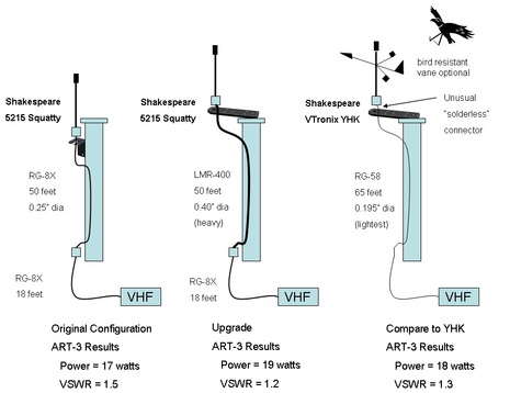
The YHK antenna was tested at a height of 10 feet above the water, with no people or metallic obstructions within 20 feet of the antenna. A Shakespeare ART-3 tester, inserted at the output of an ICOM-M422 25 watt VHF radio, was used to measure losses of the entire antenna system. The ART-3 measured 18 watts of power (larger numbers are better) and a VSWR of 1.3 (smaller numbers are better, 1.0 is optimal).
The ART-3 — which was once tested here on Panbo — was also used to measure the losses of the author’s antenna system on a 39 foot Beneteau sailboat. The antenna system does have a connector mid-length in the RG-8X coax, at the base of the mast, allowing the coax to be disconnected whenever the mast is removed. The ART-3 measured the factory configuration for the sailboat, using a total of 68 feet of RG-58X with a Shakespeare 5215 Squatty antenna, 17 watts of power and a VSWR of 1.5. Not as good as the YHK, despite the larger and better width coax cable. Clearly the smaller cable and unique solder-free connector is a winning combination.
The ART-3 was also used to measure the losses of the author’s improved antenna system, with an upgraded coax segment from the base to the masthead made of LMR-400 coax cable. This type of cable has much better performance than RG-8X cable, but is extremely difficult to bend or snake through a mast. The ART-3 measured 19 watts of power and a VSWR of 1.2. This is marginally better than the YHK antenna and cable combination, but with a huge weight penalty. (LMR-400 is easily 3 times the weight of the YHK antenna per foot, and has other disadvantages as well)
Clearly, the Shakespeare YHK antenna succeeds in its design goal of creating an antenna system optimized for sailboats, and the wicked light coax cable is not a problem as long as the installer can avoid cutting the coax at the deck. As a bonus, owners can benefit from having a wind indicator with a built in bird deterrent (the metal antenna whip) which prevent birds from landing and causing damage.
– Dan Corcoran is an avid sailor and leads ServiceSPAN a back office work center automation technology company.


It’s nice to have only one mount point for both the antenna and Windex. Also, the mounting bracket is plastic, so there is no need to DC isolate the antenna from the mast. I have used one for a year with no problems so far. But don’t leave the Windex on it’s side facing the sun in the back seat of your car or it will warp!
Cheers,
Noel
One of those “why didn’t anyone think of that before?” things.
Very cool.
Not sure I would trust a solderless connection when it is that high up on the mast and difficult to get to.
Dan, don’t I recall from your draft that you got some odd ART3 readings when your body was too close to a test antenna? Other antenna testers might value that lesson.
It is not really fair to compare an instillation with brand new coax to one with existing (read old) coax as coax deteriorates with age.
I realize that you were not attempting to do a rigorous, scientific comparison. One point to consider however is that it is not the power into the coax that counts, it is the power that makes it out of the antenna that counts. If you take an old roll of high loss coax and test it you may find that it accepts even more power than any of the antennas tested, even without an antenna connected.
Just keep in mind that RG58, and even 8x for that matter, won’t meet ORC Offshore regs for signal loss on most racing sailboats over 40 feet.
These are very whippy antennas. With the windex halfway up them they tend to move around a lot. Ours came without a way to hold the windex down, just up. The windex would work it’s way to the top of the antenna in heavy swells and the entire antenna would whip like crazy. I added a hold down and that settled the assembly well.
Sent from Asylum located at 42 south 145 east on a beautiful day enroute to Port Davey on the south coast of Tasmania
This looks like an improvement on the Glomex RA111AIS unity gain antenna. It has enough cable to make the mast run and boat run (for my 37′) such that with only two connections there is less signal loss and less chances for cable corrosion.
The Glomex as I recall had a unified antenna/cable. No connector. I couldn’t/wouldn’t use it because the cable was too short. Someone in Glomex marketing should be spoken to in a firm voice.
Chris
ORC regs require 15 watts be delivered to the antenna. Radio to antenna, RG58 is good for 38′, 8X 47′ and RG8 85′. Coax cable loss is easy to calculate:
http://www.timesmicrowave.com/cgi-bin/calculate.pl
We spec LMR type cable for lower loss. It is also less susceptible to deform when hanging under its own weight, thereby maintaining the all important 50 ohm impedance.
R.e. the inline watt meter. It is an indication of performance, but when located at the radio it tells us how well the antenna circuit is matched to the radio transmitter.
Yes, right Ben, I have two comments to share about the testing.
1. Originally I planned to field test the YHK antenna atop the mast of my 39 foot sailboat, but got cold feet when I realized how wicked thin and lightweight the included coax is. I instead elected to test this antenna ashore, and went about upgrading my existing coax from RG-8X to LMR-400. While the LMR-400 yielded a big improvement, I now have many regrets based on the ART-3 measurements. If I had chosen the YHK I would have (i) had nearly the same performance improvement, (ii) saved $50 on the installation, (iii) saved five hours of labor dealing with the very inflexible LMR-400 cable, including drilling new access holes at the top of the mast and in the deck to allow for the necessary increased bending radius required for LMR-400.
2. I learned something about testing antennas through this experience. My original results when testing the YHK were unbelievably erratic. After consulting with Donald Henry over at Shakespeare, I learned that the proximity of the human body affects the measurement of VSWR considerably, in my case as high as 3.0, and that such testing needs to be done with the antenna 10 feet or more away from people. That makes me wonder how well AIS antennas perform on sailboats when they are mounted on the stern rail of a cockpit with people closer than 10 feet. Does anyone have an answer?
Reply to Jonnyboats: Good point given what I wrote. I should have communicated that I have been taking readings of my sailboat with the ART-3 since shortly after I purchased her new in 2006. For all these years the reading has been unchanged from the one I provided, so you could view that reading of 17 watts, 1.5 VSWR, as being the same for a new RG-8X.
Reply to RoyHB: That’s good real world experience to consider. Question for you, as nearly every sailboat comes with a standard method of installing a windex, I was curious why someone would install the weather vane option. What was your reason ?
Other note: I thought the feature of the antenna serving a deterrent for landing birds was neat. In writing the article I checked out the Davis product, and found they offer the bird deterrent two ways, the second one I purchased:
Windex AV – An windex designed to be installed on Shakespeare and Metz antennas
Windex 15 – A standard windex inclusive of a metal spike to prevent birds from landing.
Always thought that a little LEd illuminated Windex would be handy. Having to run the tricolour to illuminate it always seems wasteful
Dave
Shakespeare specifies 65′ of “special low-loss RG-58 coax cable” is supplied with the antenna.
Belden RF200 (RG-58) is “low loss” cable would meet the OSR 3.29.1.b.iii “not more than 40% power loss” requirement for up to 80′ at VHF frequencies (2.9 db attenuation / 100′).
I don’t know what Shakespeare is supplying, but there are several other brands which also would also satisfy the OSR regs.
Cheers,
Noel
Belden is anther example of a low loss coax mfg. The RF200 is similar to LMR200.
A 40% loss = 2.22db. At 156.800Mhz (channel 16), LMR200 is good for 55′, not including insertion loss from connectors. RF200 is slightly better, but doesn’t get you over 60′.
Dan, don’t be disappointed from installing LMR400, it is doing a much better job than the standard marine coax you replaced. LMR400 is stiff, which can be a challenge with some installations. The ART-3 reading would not necessarily change with new coax. In fact, by changing the coax and seeing similar reading, it may point to an antenna, antenna environment or a bad connection issue that is reflecting power back down the coax.
Eric, did I misunderstand the readings, does something seem amiss between the readings and the cable types ? Do I have room for improvement ?
(Keep in mind, this isn’t an apples to apples comparison. The lack of a mid-span connector in the YHK cable likely helps it score much closer to the LMR-400 than it would otherwise. )
I’m sorry Dan, but there are a lot of errors in this article, an your conclusion #1 in your comment is also incorrect, the positive side is that your new LMR installation for sure is much better than the YHK kit.
The ART tester can NOT measure the antenna’s “efficiency” (that should be called gain), or the losses in the complete system. It has no idea whatsoever of the attenuation of your coax, quite the opposite, a lossy coax will give better SWR and a good one will give poorer SWR with the same TX and antenna.
The ART, just like any simple SWR meter, measures the output from the radio, and the reflected power. Nothing else. It does NOT measure how much of that power is actually transferred out FROM the antenna.
Look at the transmission system like this:
1. Power goes out from the radio.
2. Some power is lost (as heat) in the cable & connectors on the way to the antenna
3. Some power is reflected in the cable (if bent too much f ex) and in bad connectors on the way.
4 At the antenna, some power is radiated, some is lost (as heat), some is reflected.
5 The reflected power from the antenna is partially lost through cable attenuation on it’s way back to the radio.
The ART, as any SWR meter, measures point 1 above, using the PWR setting, and the sum of the reflections, minus attenuation, that reaches the radio again coming back, in the SWR setting.
Now, that means that a high SWR is never good, but a low SWR is no guarantee that the system is optimal.
– A lossy coax is not detected, quite the opposite. A lossy coax will attenuate the signal both going up, and the reflection coming down, so an antenna with 1.5 SWR may very well read 1.2 with a lossy coax and 1.4 with a better coax, but more power will actually be transmitted with the better coax.
– An antenna’s gain is not measured, only it’s resonance. You can make a very short antenna almost like a coil, that radiates badly but does not reflect power either, and you will get great SWR, but terrible performance. If you attach a dummy load (a screened resistor) instead of the antenna, you will get perfect SWR and NO transmitted power.
So considering the above, SWR measurements is of no use in trying to compare different (but working to spec) antennas and cables. It’s only useful to detect if your antenna has gone bad, it should be used relative to an eralier measurement on the same setup, or as a confirmation that an installation is OK.
If You want to know the ABSOLUTE performance of the antenna system, you MUST use the SWR figure as just part of the equation, the other factors beeing the gain of the antenna (true gain, measured in dBi or dBd, not the marine-dB BS some manufactures has come up with), and the coax attenuation at VHF freqs. There are no shortcuts.
To actually measure the radiated power would require an antenna range and equipment to measure field strengths in a sphere around the antenna, not something that can be accomplished practically on a boat. It’s what the antenna manufactures do (or should do) to be able to publish gain figures and radiation patterns.
BTW, I consider Shakespear, Vtronix and Glomex all rather low-quality judging from the products i’ve seen.
Really good antennas are for example made by AC-Marine, Procom, Comrod and RR Electronic)
/Marcus
PS: I worked for many years for an antenna manufacturer that had one of the largest and best equipped indoor antenna measurement facilities in the world, but not one of the above mentioned. No commercial relation.
Marcus’ forward/reflected power explanation is great!
And pay attention to his mention of antenna gain ratings – db, dbi, and “marine db.” They are not the same (like apples and oranges), and one is pure BS.
And again, he’s on the money regarding quality antenna manufacturers – AC Marine, Comrod, and Procom are top notch.
Eric,
Belden RF-200 (per spec) = 2.9db / 100′ = 2.2db / 76′ = 40% = OSR legal. I don’t think ISAF will question Belden’s specs.
Cheers,
Noel
Noel, I believe 2.9db is at 100Mhz. As freq rises, so does attenuation.
Assuming RF200 = LMR200 performance (they are nearly identical), at 156.8Mhz, attenuation is 4.1db per 100′ which gives the results I started earlier.
Marcus, you have raised some excellent points and communicated them really well in your comments. I encourage other readers to look at your comments carefully. You really nailed many points well as I now understand what you wrote. The most surprising for me was that when taking the SWR reading with the meter positioned at the radio end of the cable, “a lossy coax may give a better SWR reading and a good coax may give a poorer SWR with the same radio and antenna.”.
Another thing I liked, is the clarity you brought to what the ART-3 can measure. I would add that most 25 watt VHF radios only put out close to their 25 watts rating when the input DC voltage is 13.8 volts (or slightly higher such as when the alternator running), and such power generally drops quickly when the voltage is lower due to either the source being lower, voltage drops in the wiring directly and/or voltage drops that are caused by other boat components that increase voltage drops as they share wiring, bus bars, fuses, and other electrical components between the radio and the battery.
An exception to agreeing on these points, is the comment about antenna’s being better made by AC-Marine, Procom, Comrod and RR Electronic. The article is about the optimization of this antenna for sailboats. I understand some serious engineering goes into matching an antenna to a specific application right down to the bracket and instructions offered for mounting, and minimizing issues like detuning. A cursory search of the internet revealed to me that those companies don’t offer an antenna optimized for sailboats as Shakespeare has that considers the antenna is already mounted very high and tradeoffs can be made to achieve a low weight and windage that matter a great deal on a sailboat masthead.
In my opinion the best performing lightweight VHF antenna for sailboat masthead mounting is the GAM SS2. In most tests I’ve seen, as well as experience with what we’ve installed, it is a better performer than the ubiquitous Metz or Shakespeare units.
The GAM ELECTRONICS SS2 antenna is not only a good performer, its mounting accessories are notably better than most competitor’s offerings. I have been using a GAM SS2 on my small power boat for several years.
Just an FYI – in the US Shakespeare is calling the model WITH the windex the 5445 and the model WITHOUT the windex is 5440. The YHK is being sold in the UK. The 5440/5445 also come with cable.
The Shakespeare 5445 is still being sold, I think, but here are two alternatives:
https://www.davisinstruments.com/product/windex-av-antenna-mount-wind-vane/
https://www.scoutantenne.com/en/windex-scout-vhf-50/
The Windex Scout VHF 50 looks well designed and made to me, and it is available here in the USA:
https://www.defender.com/product.jsp?id=6792185