
Charging LiFePO4, what’s the impact of lower voltages?
What voltage should I charge my LiFePO4 batteries? That seems like a simple question likely to have a single, direct answer. But, the actual answers are often unclear. Many LiFePO4 battery manufacturers recommend 14.6 volt absorption. But, that singular recommendation doesn’t account for numerous factors like managing a larger system, battery longevity, and more. Increasingly, we are seeing good reasons to lower charge voltages to 14 volts or below. But, what impact does that lower charge voltage have on capacity and charge time? Let’s take a look.
Recently in my testing I have seen several 12-volt Epoch Batteries equipped with a feature that disconnects charging when the BMS sees charging over 14 volts and under 3.5 amps. This feature attempts avoid damage to the battery from extended high voltage charging. But, it also comes with some unintended consequences as charge sources aren’t designed for disconnection while charging.
Preventing charge disconnects isn’t the only reason to use a low absorption voltage with LiFePO4 batteries. Rod Collins of MarineHowTo has long advocated for lower charge voltages. In fact, he has a 15 year old, 400 amp-hour battery he built back in 2010 that he exclusively charges at 13.8 volt absorption. That 15 year old battery has done more than 2500 cycles and still tests over 103 percent of rated capacity.
LiFePO4 battery manufacturers regularly call for an absorption voltage between 14.2 and 14.6 volts. So, what are the ramifactions of charging at a lower voltage? First, keep in mind that in lead acid batteries we use a relatively high absorption voltage in order to put some heat into the batteries and sluff off any sulfation that may have formed on the battery. With LFP batteries, that isn’t a concern or necessary.
So, the two main factors likely to be impacted by lower charge voltages would be capacity and charge time. Specifically, we want to know if the battery delivers less power if charged at, for example, 13.8 volts than it will if charged at 14.4 volts.
Testing capacity and charge times
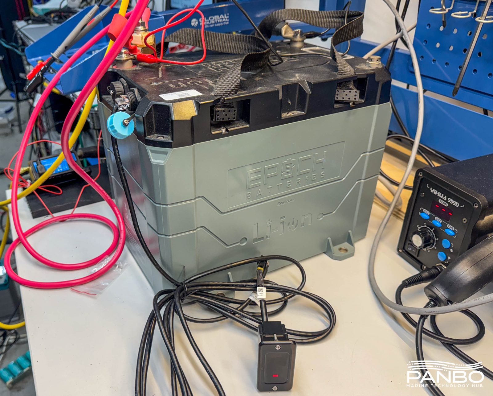
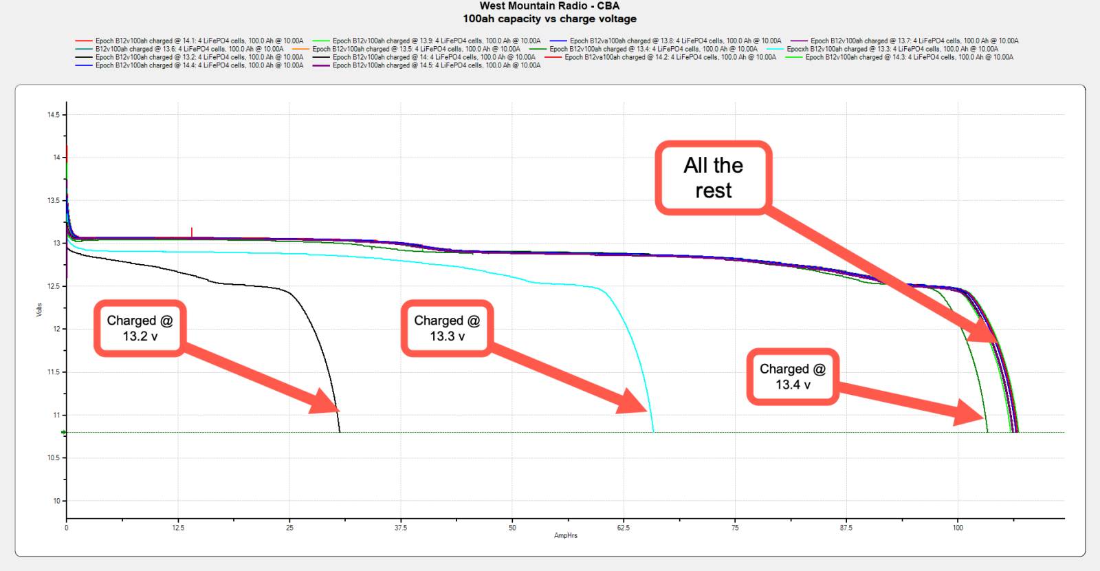
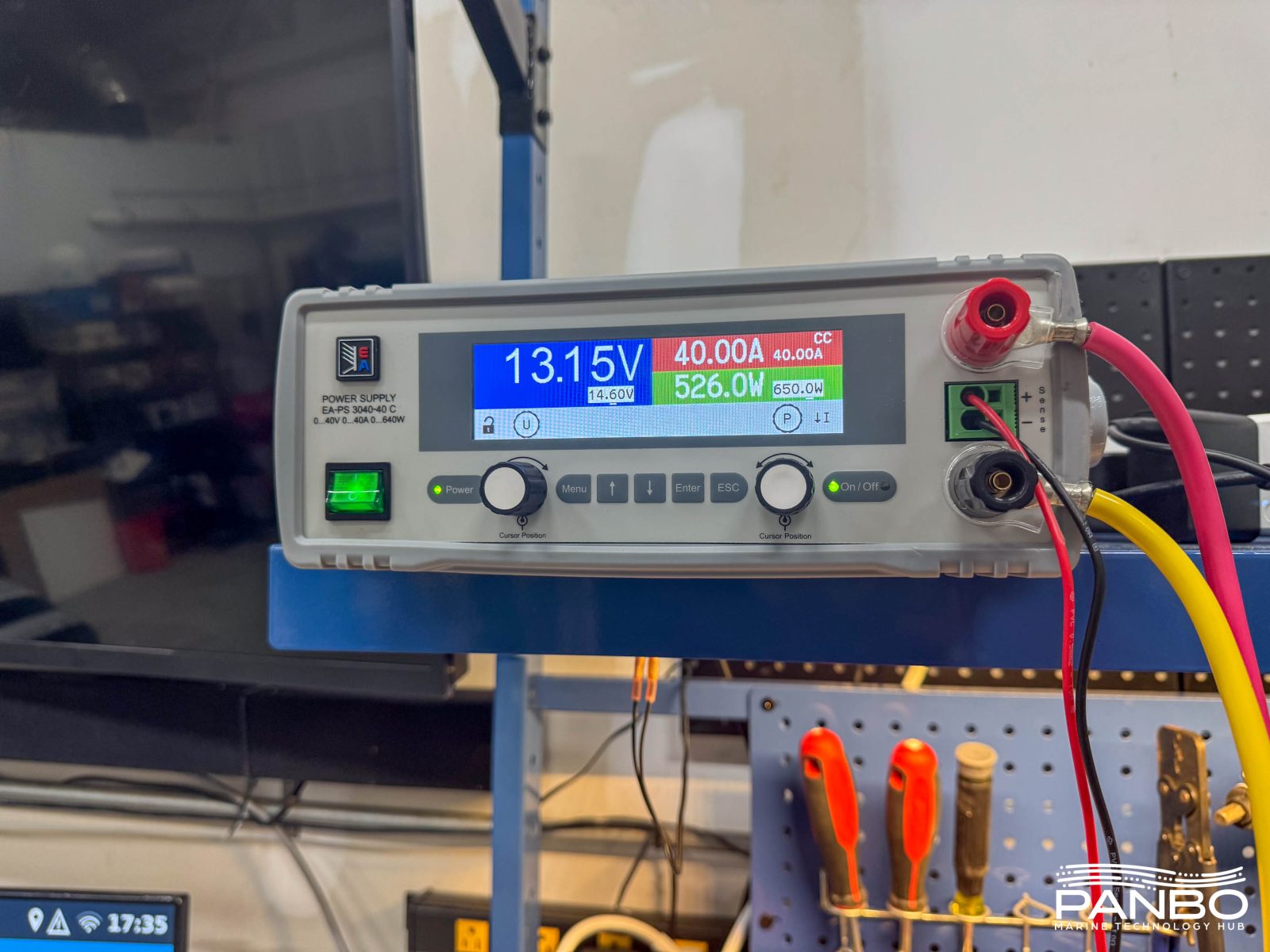
To understand the impact of lower voltage charging, I’ve done a series of tests with a 100 amp hour Epoch 12-volt battery. I reviewed these batteries early last year — and missed the full charge disconnect feature — and found they regularly delivered well over their rated capacity. Using a 40 amp, electronically controlled power supply, I fully charged the battery from 13.2 to 14.2 volts. My power supply uses sense leads to ensure the battery measures the correct voltage at its terminals.
I then tested the capacity using a 10 amp discharge rate. Effectively, this is a 10 hour capacity test for this battery. That’s more aggressive than a BCI 20-hour capacity test but gives a basis for comparison. I selected a 10 hour test just to try and minimize the time required to complete the tests. I don’t expect the capacity numbers would be very different with 20 hour tests. LFP batteries have a much lower Peukert’s exponent than lead-acid; meaning the discharge rate has a smaller impact on capacity.
| Charged voltage | Capacity @ 10 hour rundown | Charge time (hh:mm) |
| 14.6 | 105.96 ah | 2:45 |
| 14.5 | 106.14 ah | 2:46 |
| 14.4 | 106.51 ah | 2:48 |
| 14.3 | 105.90 ah | 2:50 |
| 14.2 | 106.56 ah | 2:51 |
| 14.1 | 106.49 ah | 2:51 |
| 14 | 106.67 ah | 2:53 |
| 13.9 | 106.89 ah | 3:37 |
| 13.8 | 106.7 ah | 3:43 |
| 13.7 | 106.69 ah | 3:59 |
| 13.6 | 106.6 ah | 4:39 |
| 13.5 | 106.15 ah | 6:15 |
| 13.4 | 103.32 ah | 17:10 |
| 13.3 | 65.83 ah | 10:49* |
| 13.2 | 30.59 ah | 8:28** |
As we can see in the data, capacity really doesn’t vary until we drop below 13.5 volts absorption. But, while capacity is quite stable, lowering absorption voltage steadily increases the time it takes to reach full charge. At 13.4 volts, it takes a full seventeen hours and ten minutes to achieve full charge. Absorption voltage below 13.4 doesn’t fully charge the battery. Using a 40 amp charger to replace 106 or so amp hours, the theoretical minimum time would be two hours and thirty nine minutes. By 14.1 volts, we are within 12 minutes of that figure and not likely to improve much due to charge taper near 100 percent SOC.
Time to absorption
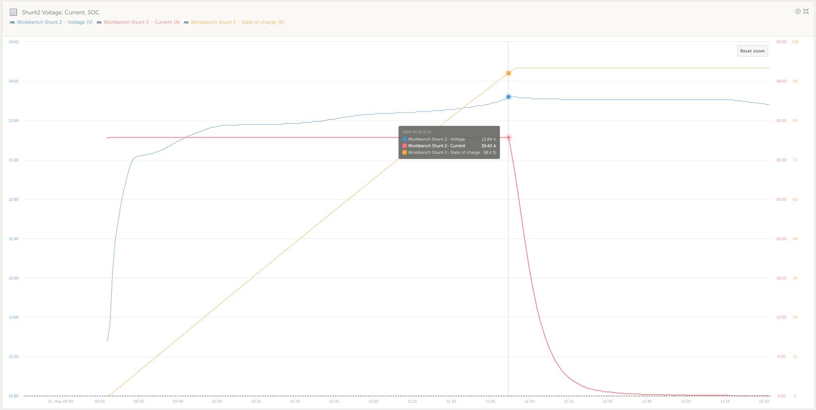
My first thought when I looked at the results was, well capacity doesn’t take much of a hit, but charge time sure does. However, it occurred to me that the additional time is probably mostly at the very end of charging as the battery has already reached a high SOC. Indeed, the chart above shows the details for charging to 13.9 volts. It took two hours and forty one minutes for the battery to reach the transition point from bulk to absorption. At that time, SOC measured at 98.4 percent. The remaining 1.6 percent took an hour and ten minutes. Effectively, that last 1.4 percent is likely inconsequential.
I was equally surprised to see how quickly the transition point moves when you decrease charge voltage. As is depicted in the graph above showing charging at 13.9 volts, by decreasing charge voltage by just one tenth of a volt, the transition to absorption or constant voltage charging occurs at 91.2 percent, a full 7.2 percent sooner. I submit that potentially missing out on nearly nine percent of a battery’s capacity is of greater consequence.
What have we learned?
If you took the time to read this article, it is probably because you’re trying to figure out charging settings for your LiFePO4 batteries. So, what conclusions can we draw from the data? Overall, I think we can conclude that a charge setting of 13.9 volts won’t meaningfully impact the capacity of your battery bank. In fact, I suspect you wouldn’t ever notice any difference in capacity. It is possible you will there will be a barely perceptible difference in charge times..


I had some idea that this would be the case, but this testing actually confirms it to an even higher degree than I fugured. I have settled on 13.9 bulk/ absorb and 13.5 float. The next question would seem to be…how does this slightly lower charge voltage affect the cell balancing on a typical drop in with passive balancing over the long term. I have noticed Litime has a similar full chg protection as well. Thanks for all the great testing Ben. Much appreciated.
Ben,
As you know I was working on this exact article but the testing takes time. I had a few more tests to run, this just saved me the time.
I will just point out that it is hard to find a charger that has less than a 1 hour absorption so 13.8V -13.9V is not going to cost you much capacity at all. I knew all this back in 2009 from testing and is how I arrived at 13.8V for absorbing my 12V pack..
Also just realized these graphs say that floating at 13.5 still keeps you very close to full capacity, while floating just one tenth lower at 13.4 has some actual capacity loss. So it appears at least for this battery, to keep SOC meters more in sync and accurate after the full charge cycle has ended, floating at 13.5 would be significantly better than floating at 13.4. Especially if floating for extended periods. I always figured 13.4 or 13.5 for float…whatever. But this data says otherwise.
In addition in conjunction with your last article on the Epoch 460 comms and DVCC, you probably could use the Victron Comms and DVCC (which we know results in a single stage charge profile) and keep the bulk/absorb/float at something like 13.6 or 13.7. I doubt holding these cell at 13.6 or 13.7 would result in adverse effects over the long term and just comes at a cost of charge time. Many manufactures state to float at 13.8. Not that I would prefer that. It would seem you would want to float at the lowest voltage that does not incur meaningful capacity loss. Which according this data is 13.5.
Also just realized these graphs say that floating at 13.5 still keeps you very close to full capacity, while floating just one tenth lower at 13.4 has some actual capacity loss. So it appears at least for this battery, to keep SOC meters more in sync and accurate after the full charge cycle has ended, floating at 13.5 would be significantly better than floating at 13.4. Especially if floating for extended periods. I always figured 13.4 or 13.5 for float…whatever. But this data says otherwise.
In addition and in conjunction with your last article on the Epoch 460 comms and DVCC, you probably could use the Victron Comms and DVCC (which we know results in a single stage charge profile) and keep the bulk/absorb/float at something like 13.6 or 13.7. I doubt holding these cells at 13.6 or 13.7 would result in adverse effects over the long term and just comes at a cost of charge time. Many manufactures state to float at 13.8. Not that I would prefer that. It would seem you would want to float at the lowest voltage that does not incur meaningful capacity loss. Which according this data is 13.5. But holding the cells at 13.7 probably has no adverse effects.
Rod or Ben or anyone…given this data what is your feeling on charging and floating at 13.7 for the Epoch 460 with DVCC back on. It seems odd. But it may in fact be just fine given this narrow window of what voltage constitutes “full” capacity vs what voltage are considered safe in the long term. I do know that many off grid guys do just that at 13.8.
Maybe these Chinese engineers do know a thing or two..lol.
Excellent information Ben!
Thank you for posting this data. Andy from Off Grid Garage has come to very similar conclusions based on his testing.
For the Epoch LFP’s there does not appear to be any advantage to bulk absorption voltages higher than 13.8-13.9 VDC but deciding on the ‘float’ voltage is less clear-cut…
The common wisdom has been that LFP does not do well with the cells held at a continuous 100% SOC. Is this still true?
Assuming the house bank will have to service ongoing loads while a vessel is on shore-power, what is the optimal float voltage to keep the house bank in a good, ready to cast off, SOC?
In other words, What is the maximum safe steady state SOC we should aim for?
I’ve seen very little evidence to support the notion that damage is done or life is shortened by holding LiFePO4 batteries at 100% SOC as long as the voltage isn’t elevated. So, I don’t think any damage is done holding batteries at or near 100% SOC with a 13.4 or 13.5 volt float. Allen asked a question about using a single stage charge at 13.7 volts and personally, I’m not comfortable with that yet.
-Ben S.
Thank you Ben.
I have been playing with a few float settings but it’s been tricky to get a float value that settles reliably into my target of ~ 90% SOC range. If being at or close to 100% SOC at 13.4 V float is OK & not harmful to the cells , that would be excellent and easily achievable.
Could you post the 14.0v to 14.4v curves that you show in the blog for 13.8v and 13.9v? The data might be easier to parse in a table but the time to get to the absorption phase and time in absorption until full (100% SOC) seems like a crucial discriminator for choosing the charge voltage.
I know many like the lower charge voltage for longevity but that seems an optimization that may be much less important to others, but having data to support these “best charge voltage” decisions seems to be the best approach. Thank you.
Thank you for this very valuable info. I know that it took a lot of time and effort to collect and analyze. There are a lot of opinions out there, few of which are grounded in as detailed analysis that you’ve provided. I spent the majority of my career working for the largest test and measurement equipment company and we had a saying which I’ll paraphrase as, “Until you make a measurement, you don’t know what the heck you’re talking about.”
Well done! Looking forward to more of the same.
Thanks for all the work you have done with the 460s which helped a bunch in my new install! Also thanks go out Allen and Jim Duke.
Ben-
Excellent and detailed investigation. As I looked at your data I had to greatly admire the details you had to overcome to collect this data over weeks of effort and then boil it all down. But I have a question. What part does the BMS have to play in this charging scheme? Doesn’t the wide variation in BMS types have a big impact on these measurements? Or are we assuming you are charging “direct” to the cells with no BMS involved? Assuming the BMS plays a role it seems that the small changes in tenths of a volt in Absorb voltage could also be related in part to the BMS control device technology – GaN FETs Vs CMOS etc with different CE (Collector to Emitter) voltage drops could have an impact on how much charge is reaching the cells. Seems like there are huge unknowns running around in the BMS in addition to the specific nature of the LiFePo cells and their varying manufacturing methods.
I have no clue how to resolve these questions. I will say that for now, my poor old brain just wants my WS500 to take care of my $5K investment in my bank of 4 – 8D old fashioned AGMs and all of this research points out that optimizing the capacity and longevity of LiFePo batteries is worthy of years of experiment and discussion.
I can see the benefit of LiFePo on sailboats in particular where there is usually far less room for huge collections of AGMs. The great capacity Vs Volume and weight provides great benefit for modest sailboats. I helped a great friend rig a nice dual AGM (Start – Motoring Battery) and LiFePo (Solar Charged) for sail and at anchor. This dual scheme only required investment in a VE MPPT solar charger and the rest of the gear on his 30HP Diesel and Charger inverter remained the same. Battery switching isolated the loads so that only one type of battery was in use at one time. He is loving it and is happily cruising the Broughton Archipelago in BC Canada now. So long as his VE MPPT keeps his LiFePo going he is happy and will never be aware of all of this research. But if he does see the battery capacity tail off I can refer him to all of this knowledge so he can keep his investment going.
Thanks tons for the work!
The only downside with the “short-charging” is that the BMS has a harder time balancing the cells. The cell differences in capacity show up when reaching full voltage.
So a higher-voltage charge every now & then is still a good idea. Just don’t leave them at high voltage for long periods; just get the voltage up >14.0-14.2 for 30min which should be plenty for balancing if done once a month or so. Then discharge them a bit, and cycle away between 13.0 and 13.8 or whatever, to your heart’s content…
Is this really true though for passive balancing? My Epoch batteries are passive balance. The final balancing that brings the cells into voltage alignment takes place overnight after the charger has been turned off. Active balancing maybe different though. I dont have any experience with it.
I think you might be thinking that the resting cell voltage is what is meant by balanced cells. (“ The final balancing that brings the cells into voltage alignment takes place overnight after the charger has been turned off.“) What you describe is the resting cell voltage (no loads) or the voltage while in the flat portion of the discharge curve which will be approximately equal because of the slope of the curve until the slope steepens near the full discharge limits where the individual cell voltages will diverge like they do in the upper portion of the charge curve.
This near equal cell voltages while not under charge and/or while at rest isn’t the same as the cell voltage delta being at/near 0mV at the end of the absorption phase (steep slope portion of charge curve), which is what is meant by “balanced cells.” The end of absorption phase cell balance is what is important for the battery to achieve routinely to prevent the faster cell achieving overvoltage protections during charging and for overall capacity/lifespan.
With regard to the epoch using the 13.8v absorption, for balanced cells you want to see 3.45v on each cell before you float or turn off the charger. The 3.xx volts you see in the morning on each cell is just the voltage in the flat part of the charge curve. You don’t need to achieve this balanced condition every day, but it should be done routinely (at least monthly).
If the cells are not balanced (at end of absorption cycle) routinely, the energy stored in the battery will be increasingly limited. (The unbalanced cells highest/fastest and lowest/slowest cells define the BMS upper and lower protection limits—not a huge problem if you don’t approach these limits but the cell voltage deviations will increase over time and this can be a challenge for accurate SOC estimations and health of the fast and slow cells as the cells diverge in charge rate and voltage range affecting the useful capacity.
Another way to think about this is you want all the cells to charge to the same voltage at the same rate and you want them to all discharge to the same voltage at the same rate…to be balanced cells. The end voltages define the goals, and it is safer /healthier to use the ending charge voltage rather than the ending discharge voltage as the measure of “balanced.”
(The Victron Smart Lithium battery manual (online pdf) has a nice explanation of cell balancing and the importance of routinely balancing the cells with sufficient time at the top of the absorption cycle. )
Ah, got it. Ok, yes i was confusing the two, that makes perfect sense. I have been charging until i see 3.45 volts per cell and then shutting off the charger at this point. I have been noticing the deviation i think your describing while it gets near the end of charge. The cell voltages do deviate quite a bit and then get to within .005 volts or so when they get near 3.45 volts or 100% SOC, but im not cruising and doing partial charge/discharges. I think I understand Bruce’s comment now and can see how maybe how partial charges/discharges might widen this gap over time.
I am using a Magnum inverter to charge my Epoch 460ah battery and have found that the charge cycle won’t stay in Bulk, but rather quickly switches to Absorb charging with a set charge voltage of 13.8. The current draw early in the Absorb cycle is approximately at my set value of 80 amps (the charge cycle looks very much like a bulk charge even though the Magnum is in Absorb). Later in the charge cycle, as it approaches the full battery capacity, it tapers to zero amps. The Absorb control is only done with a time setting so the display will show Absorb charging at 0 amps. The battery and shunt confirm there is no current being supplied for charging even though the display still shows the absorb cycle is still ongoing. It takes approximately 3 hours to recharge the battery with these settings. I have the final charge on the Magnum set to Silent, so that the charger shuts off completely until I hit my Rebulk setting of 13 volts. If I don’t use the Silent final charge setting but rather use the Float, the rebulk is 12 volts by default and that can’t be changed. Once the charge cycle enters Silent mode, the Magnum will then draw 2.1 amps from the battery to monitor for the next charge cycle that occurs in about 5-6 days. Even though I am using the Custom setup on the Magnum, the settings make it behave like it is CC/CV charging.
Hi Bob,
I only use my Magnum for bulk charging on the generator.
It’s Much simpler to use a reasonably cheap and much more programmable Victron IP22 while on shore power to maintain the Epoch’s while docked at home.
Great article and great analytics Ben. Thank you. Using a bench supply makes sense for this testing. In the real messy boat world of multiple charge sources there are a lot of trade-offs. What I am finding is when charging from alternators (either my 100amp engine alternator or from my 6HP Kubota 12V genset/scuba compressor (homemade setup) if I set the charge voltage to 13.9 vs 14.2, there is a very significant difference in the amps flowing to the batteries. In this case, the charge time difference is grossly exaggerated with lower charge voltages. I am using a alternator regulator that monitors both battery and alternator amps and of course alternator temperature (my improved version of Bill Thomason’s open-source VSR Alternator Regulator). At 13.9 volts, the charging is limited by the voltage. At 14.2, it tends to be more limited by the alternator temperature feedback, while providing a lot more current (almost twice as much). So from a diesel fuel and engine wear perspective, the higher voltage may win. Your thoughts?
Pete,
I can’t say I’ve tested this, but I strongly suspect the issue is the location of voltage measurement. If the alternator is being regulated to produce 13.9 volts at the alternator, you will likely find significantly lower voltage reaching the batteries. I suspect that lower voltage at the batteries is what accounts for the big delta in current acceptance and hence charge times. The bench supply I use has remote voltage sensing. If I use another one that doesn’t, I often have to boost voltage to keep charge acceptance in range.
-Ben S.
Hi Ben, I think I did a poor job of communicating my observations… let me try again. First though, to your comment, of course I am using dedicated, twisted pair, remote voltage sensing for my ‘VSR Mini-Mega Alternator Regulator” (Which is based on the open-source design that became the commercial product known as the WakeSpeed WS-500 which Panbo reviewed a long time ago). (I wouldn’t be much of an EE if I didn’t at least to that…) So back to my observation…
It really boils down to this… assuming the battery can accept both the voltage and current, as a LiFePO4 battery can as compared to a lead-acid battery (Gel, AGM, etc), then as the alternator field current is increased, BOTH the voltage AND current increase from the alternator. So, when we decide to charge at a higher voltage, the alternator will also generate more current, unlike in the fixed-current bench test that you used in your excellent article. So, in the real world, using an alternator, increasing the charge voltage also increases the charge current so the charge time dramatically decreases in more of a geometric curve than a linear one, unlike in the bench test illustration. (Do you disagree?)
Now further, as I use this “VSR” regulator with BOTH battery current and alternator current shunts (whereas most regulators have neither…), I (and the regulator) can see both currents (current to the battery and current from the alternator) and manage the charging accordingly. I therefore also set a battery current limit for the battery bank, an alternator current limit for my 12V genset, and a separate alternator current limit for my engine (that is, with the engine and genset each having their own dedicated VSR regulators). So, back to the real world… I can for example, set the battery charge current limit at 250 amps, the genset alternator current limit at 125 amps, and the engine alternator current limit at 100 amps, leaving another 25 amps of “headroom” for solar charging (250-125-100 = 25). It is, with these settings, then be possible to run both the engine and the genset simultaneously and on a sunny day charge the batteries at a rate of 250 amps, which is still way below the charge current limit specification of the battery bank. And what I find when I test this is exactly that… the alternator controller manages the alternator current at these limits (which, incidentally is also within the capabilities of my alternators without going beyond the thermal roll-off settings I have set on the alternator controllers) and see exactly 125 and 100 amps from the respective alternators and a number a bit higher than that flowing into the batteries when the sun is overhead. Why all alternator controllers don’t work this way is beyond me.
Pete,
Glad to hear you are using remote voltage sensing. With that additional detail layered in, I think you’ve provided a great real world data point about the mix of alternator charging and solar charging. There’s no question that the means of power generation or conversion matters when it comes to understanding the behavior. You’ve provided an important distinction between the toroidal transformer in my bench power supply and rotary power created by an alternator.
In cases, like what your example with alternator charging, where current and voltage move together, I would indeed expect non-linear changes in charge times as they decrease. Frankly, I haven’t been able to do enough controlled testing with alternators to say any more with confidence. I’ve been working to figure out a way to include controlled alternator testing for quite some time. I think it’s high time I step up those efforts!
-Ben S.
Hi Ben.
Thank you for the great work and sharing your findings.
Kindly note that I am not an expert in this field at all. I just have some issues with my system and thought that you might be able to help me.
I have 4 12.8V/280Ah LiFePo4 batteries connected in series for a 48V system. I have 12 solar panels (250watts/30v/8ah each) and I have these panels connected 3 in series kicking about 1600 watts, 70 v and 17 amps to my Victron 150v/70ah charge controller. The issue I have is that the batteries will show fully charged at 100% SOC and the charger will go through the Bulk, Absorption then Float stages and battery will be at 54v. But as soon as the charge is disconnected (when the sun goes down) then the batteries drop to 53v and 64% SOC within 30 minutes. It remains between 52.5v to 53v for a long time though.
I am very confused to why it drop so quickly from full charge at 100% SOC and 54v to 64% SOC and 53v? I would truly appreciate your support in helping resolve these issue please. Kindly note that my batteries are brand new, only 4 months old. Thank you in advance for your time and assistance.
Cheers!
DJ,
What batteries do you have? Also, when you quote your SOC, what is measuring that SOC? A drop from 54 to 53 volts sounds normal, but losing over a third of the capacity is definitely odd.
-Ben S.
Just like Ben’s bench power supply with v-sense, a properly wired voltage regulator will not limit current until absorption voltage is reached.
@Anonymous… Not exactly correct. With MOST regulators which only monitor voltage that’s true. Notice please that the VSR regulator uses not only voltage and temperature sensing but also current shunts on both the battery and the alternator As such, the alternator output is primarily managed to the regulator’s setting value for maximum alternator current, which is secondarily reduced if the setting for alternator temperature is exceeded. Then the battery maximum current is considered (taking into account multiple simultaneous charge sources. And finally the voltage limits the charging cycle stage, taking current down to a float level when the target voltage is achieved. The alternator field current is adjusted using a OID algorithm which Al Thomason developed in open source.
This is the ideal charging regulation which regulators with two shunts cannot possibly achieve.
Edits… PID. Not OID.
“without two shunts*cannot* achieve
Edits… To my comment… PID. Not OID.
“without two shunts*cannot* achieve
I’m using Battleborn LFP batteries and per their technical support the BMS does a top end cell balancing that doesn’t kick in until 14v. They recommend a 14.2-14.4v absorption voltage to ensure cell get balanced. While off the grid I try to get to 100% SOC at least every 2 weeks to ensure cell balancing.
That’s interesting William and very useful for folks with Battleborn batteries to know.
When using the “generic” BMS systems, like the JBD or Overkill Solar brands, they can be set to balance only while charging or while charging/not charging. So folks using “home built” battery banks have more control of things (many, many potential settings besides just this one) and the cells balance pretty much any time they need to.
Good data to know.
In my thinking every 2 weeks seems like a bit much (unless you need 100% of your battery) as charging to 100% isn’t great for your battery so you’re likely to get a little longer lifespan by only charging to 90-95% and balancing a few times a year (unless you’re seeing serious cell voltage drift). With my battery capacity and typical needs I’ve been charging to a bit over 80% and topping things off now and then mainly to make sure my battery meter’s SOC stay in sync.
All that said with the thousands of expected cycles I don’t think topping off batteries or holding your batteries at 100% or 80% or storing them at 50% is going to be critical… calendar aging is likely to be the main factor in many cases.
Are you charging the Epoch with the Balmer MC-618? If so would you share what parameters you are using with it? I took the leap and have installed two Epoch 300Ah and in the process of upgrading from an MC-614 + DuoCharge to an MC-618 + DuoCharge in a system that was all AGM. Now will be house lithium with single AGM charged by the DuoCharge.
Belay that – I’ve programmed an MC-618 to charge the pair of Epoch v2 300Ah using the 13.9/13.5 parameters – will report back. Also have solar and shore victron programmed with the same.
Rob, I’m about to upgrade my house bank next month to lithium from AGM and sound like I have a similar setup, with a MC-614 (170A Balmar alternator) and a pair of DuoCharge devices going to the start and windlass batteries. (I’ll be charging the lithium with the alternator, and installing a ArgoFET to provide load dump protection.) My question to you is what setting(s) are you using on the DuoCharge going to the AGM?
What is your understanding of the operation of the DuoCharge? Isn’t it simply a 30A limited electronic automatic charging ‘relay’, and not a true DC-DC charger with charging profiles? While it has different battery chemistry settings, I think it just changes the cut-in voltage, and doesn’t change a profile. If you’re only bulking the lithium to 13.9, and floating at 13.5, I “believe” that’s the maximum voltage that the AGM will see, which is nothing close to the absorption voltage that AGMs want to see, and certainly not the duration. Or, do you have a higher bulk/absorption voltage on a solar MPPT to help satisfy AGMs desire for a higher voltage?
If anyone else wants to chime in on the Balmar Digital DuoCharge’s operation, and suggested configuration, please do so!
The DuoCharge can step down voltage but not step it up. I’ve been running for a while with the lower voltages mentioned in this article but it has led, I think, to under charging my AGM starter (fortunately I have an emergency switch to use the house to start). I’ve changed both the DuoCharge (which feeds the engine AGM) and the MC-618 (which feeds the pair of 300Ah Epoch house) to the voltages in the Epoch manual: 14.2 Bulk/Absorb, 13.6 Float/Storage. My thinking is 14.2 should be enough to keep the AGM up as the West Marine label says charging from 13.8 to 14.6. More specifically I set the DuoCharge to its default AGM and then lowerred the High Voltage to 14.2. Hopefully the AGM will come back to life with the increase from 13.9 to 14.2 voltage charging. Many AGM’s specify higher charging voltages in which case it would be better to get an actual DC to DC (ie Victron Orion) that can step up to the required AGM starter voltage leaving the alternator regulator to serve the lower Lithium voltages. If in fact this doesn’t work on my AGM starter then I’ll probably switch out the DuoCharge for an Orion…
I’ve called Balmar and they’ve confirmed that it’s essentially a Automatic Charging Relay. It does not have any charging profiles. It simply sets cut-in and cut-out voltages of the “relay”. Essentially, any time the voltage is above 13.0V, it will “provide charging current to the starting battery”. So, with the input connected to a house lithium bank, and with lithium resting voltage around 13.5V, the DDC will always be connected to the load (start battery, windlasss battery, etc.), regardless of charging or not, any time the lithium voltage is above about 13.0V. When I spoke to Balmar, they never thought about that and concurred that I was right in thinking that I should raise the setting of the lower voltage on the DDC to around that 13.5V so that the lead isn’t ‘charging’ if nothing is charging the lithium. The not so good news with the charging sources (other than the DDC) set to a lithium profile, it will get to 14.2V, but will very quickly drop down to 13.5V float once 14.2V is achieved. Lead likes to be held at that 14.2+V absorption stage for 2-3 hours, not just 5-15 minutes. Yes, it would appear that the best thing to do would be to switch to a DC-DC charger if the AGMs die again with this sub-optimum charging method. I’m hoping with a solar daily brief bulking of the lithium to 14.2 and floating at 13.5, that the AGMs will find it acceptable, although not optimum.
Great info – thank you for getting to the bottom of it! I’ll do the same. I have a bunch of solar on board as well so hoping it will do as you say as well.
So the underlying prismatic cells are catl I believe, and in their guidance it looks to double the rated capacity of the cells by restricting the charge down to 80% (6000 cycles). I am charging to 13.34v and cutting out on my epoch as that’s kinda where I calculated 80% to be. I’ll never even hit the rated cycle count based on how seldom I use my boat, but Im going down this path anyways.
The Roy Pow built Epochs use Eve cells. Not charging to upper 13s or 14 volts means no balancing will occur in the battery. To me, that’s a much greater concern than ticking off a cycle. 3,000 cycles is one cycle a day for 300 out of 365 days a year for TEN years.
-Ben S.
I think both strategies make sense though depends on use case. I figure most LFP batteries will likely loose capacity from calendar aging rather than excessive use so are we’re splitting hairs here?
My thinking is if you’re out on your boat and/or likely to need over 80% or 90% then definitely charge to 100% (which you’ll likely get because your batteries are fully balanced). When not cruising I’ve been charging/holding my batteries around 80% and so far they are staying balanced. I know this because I do top off before a cruise or when I want to make sure my SOC is in sync/accurate.
Do you sleep better knowing that your cells are balanced within 0.4% rather than 1.9% of each other or that in 10yrs you’ll be getting 94% of their rated capacity or 92%? Seems either way is fine and I do like seeing 100% charge. Maybe this concern is left over from old lead acid habits/debates … fun to talk about. I’m still amazed how much better these batteries are than my old lead ones… as long as I don’t trickle charge them at a high voltage.
Splitting hairs? Probably! But, it’s not about achieving balance for balance’s sake. During normal operations, the most common (though that doesn’t make it common) cause of a disconnect is a cell going over or under voltage. If the cells aren’t balanced, that likelihood increases. Every battery is going to have laggard and runner cells, the variances may be small. But if they aren’t corrected, over time the delta will get larger and potentially large enough to trip a protection parameter in the battery. On the water, that’s an undesirable outcome.
-Ben S.
Excellent safety point though if any cell is regularly drifting more than just a few % out of balance there may be larger issues at hand – like poor quality cells or charging/discharging at too high of a C rate for the battery.
At the 100% risk of repeating myself, for those who want to set and forget, 100% charge definitely seems like they way to go (I would say required method if you can’t track the individual cell voltages in your battery).
The other approach requires more attention/time – keeping the SOC between 15-85% and only balancing as needed (but well ahead of any significant imbalance). aka, baby them.
In my experience topping off / balancing once every few months has been more than enough but you mileage may vary. (This attention to detail absolutely seem like overkill to me but since I have a computer onboard which monitors & logs the battery state in an influx database, automatically ‘tops off’ to 85% weekly – and remotely can charge to 100% whenever I want I have fun with it all. I do enjoy seeing my cell voltages within something like 0.008v of each other a 100% SOC)
Short version: typical boater, just keep your cells balanced/topped off – if you still have them in 10 years you likely won’t even notice the few % capacity loss, if there is any. For those who have too much time on their hands & baby them, in 10yrs (even if your cells are 2-3% out of balance), you may get slightly more power from your battery than someone who balanced everyday. Either way we’ll have something to talk about … sure beat this one today 😉
I tried new charging parameters this last cycle changing the charge voltage from 13.8 to 14 volts. Unfortunately I don’t have a way to log what was happening but I believe one cell ran away and the BMS shut down the charging because my Magnum still showed absorb charging but at zero amps. My cells were pretty well out of balance compared to when I charge with 13.8 with around 5% difference between the high and low. I have since gone back to my normal charge at 13.8 volts.
Sorry, didn’t notice I didn’t identify myself when I submitted my comment.
Bob T
5% individual cell voltage deviation (.17v) at any part of the charge cycle (at end of absorption, or worse, after end of absorption at float or when at rest) signals that your cells really need to be balanced—badly. As you found, the “runner” likely hit a protection (full charge, or cell over voltage (OVP)) when you pushed it a small amount further. Should you not manage the cell balance,— long absorption at 13.8v where each cell, at the end of absorption, is fully balanced (3.45v each—some call this full full full) you will likely run into this same behavior at 13.8v charging (OVP) as the runner and laggard diverge.
Even a much smaller deviation should be corrected and managed. One LFP maker recommends 8 hours in absorption monthly is a good rule of thumb (and they use passive AND active balancing). Even though passive balancing works, it only works well when there are small charging currents as the bleed resistors are relatively small compared to the charging pressure until the current tapers.
Cheers
Thanks for the input. How do I balance the cells with my Magnum, is it just a matter of leaving in absorb for an extended period? I did leave it in float for a month only because I didn’t want to cycle the Magnum in the extreme heat, now that it’s cooled off I am not using float but silent (Magnum won’t charge until it hits the rebulk setting). I did see when in float for that period the cells were getting farther apart. When it comes off of a charge the cells balance fairly quickly.
Hi Bob,
I have a Magnum charger but only use it for its bulk charging capabilities (CC/CV) while on the generator and it’s in use as my inverter off grid.
Its charging programmability is otherwise too limited.
While on shore power, I use a Victron IP22 charger that is fully programmable and can use the Smartshunt data (BMV 700) to guide its parameters. The IP22 is quite cheap but very customizable as to bulk, absorption, float & storage parameters.
(I actually have 3 of these IP22’s in parallel for increasing capacity on the generator but only keep one in service while on shore power.)
This all works very well.
Not sure if you saw my comment below, curious if you have any issues with the CC/CV setup? It basically operates the same as the way I have my Custom setup with a charge finish of Silent. I have thought about using a separate charger for the lithium, but haven’t sorted out how to set it up since my battery is in an RV and the Magnum is hard wired to the transfer switch. I might be able to set the Magnum charge parameters out of range of actual charging so it doesn’t start a charge cycle allowing the Victron to handle the charging.
The CC/CV Profile works very well for bulk charging when needed (ie maximum output when charging on the generator); but, I turn off the Magnum charging when the boat is on shore power leaving this to the 30A Victron IP22’s.
Bob, you must have a very old magnum inverter/charger as I have one from within the last 4 years and can set custom battery charging parameters. With 12x50Ahr24v battery bank I set bulk voltage at 28.8v and 2 hr absorption. I was originally having the charger go into silent mode and rebulk at 26.2v but now I just float at 26.4v which generally keeps the SOC at about 60%. If going out cruising the 190 amp alternator brings to 100% SOC with only 1-2hrs cruise.
My Magnum is now 10 years old. I do have it set on custom, but it only stays in bulk for a very short time and most of the charging is done in absorb when set at 13.8 charge voltage (that’s why I tried the higher charge voltage of 14 volts). I believe this is because it doesn’t have separate voltage sensing and it misreads the voltage when the current is high. The battery and my shunt definitely show lower voltage when the current is high in the early charging. The absorb charging is done at the higher current (I have it set for 80% or 80 amps) which then tapers down as the battery reaches full charge. I have spoken with Magnum and they stated what the charger is doing is normal.
I will need to put it back in float prior to our trip because I can’t let it get too low prior to departure since my alternator charging is limited by the Victron DC-DC charger. Although it will charge at 30 amps, depending on what we have for current draws, I may not get a full 30amps to the battery if there are other DC draws on the alternator.
Just think that well within ten years the lipo’s will be an obsolete storage battery. Then those that can will get the latest. This is very dynamic industry. I have been working in battery/ev technology for over 60 years so have learned patience and worry over batteries is not really worth too much. I applaud this research but enjoy your boat especially if it sails.
Really helpful and thorough research, same goes for the comments, thank you very much. I’ll be ammending my absorption and float rates as a result of your work.
Hello Ben,
Very useful information – thanks very much!!
Do you know the balancing requirements for the Epoch 460? I think it is top end, passive balancing but I have not been able to confirm this with Epoch (they always say “we’ll get back to you right away” but never do).
The big question is requirements for a charge source while balancing. Will this battery balance if it is charged to some level and then the battery is disconnected (say by a battery switch)? The motivation for this: there are some devices on the market that claim to intelligently parallel lead acid with LFP. One of the characteristics is to disconnect the LFP, based on terminal voltage sensing, via a contactor. I suppose this might be OK if the battery will perform cell balancing while in this disconnected state.
The Epoch 460 is passive/shunt balancing..
Terrific article! Any thoughts on using a fixed 13.5 volt setting on my Kisae Inverter/Charger for shore power? It doesn’t provide the ability to set specific values and so my only other option is to go with the lithium preset options with absorb at 14.2 (or higher) and float always at 13.8. I also have Victron MPPT and DC-DC chargers for solar and alternator power that I can configure more precisely and use to deliver a higher absorb charge.
Hi Ben
Thank you for the great work and sharing your findings.
Kindly note that I am not an expert in this field at all. I just have some issues with my system and thought that you might be able to help me.
I have 4 12.8V/280Ah LiFePo4 batteries connected in series for a 48V system. I have 12 solar panels (250watts/30v/8ah each) and I have these panels connected 3 in series kicking about 1600 watts, 70 v and 17 amps to my Victron 150v/70ah charge controller. The issue I have is that the batteries will show fully charged at 100% SOC and the charger will go through the Bulk, Absorption then Float stages and battery will be at 54v. But as soon as the charge is disconnected (when the sun goes down) then the batteries drop to 53v and 64% SOC within 30 minutes. It remains between 52.5v to 53v for a long time though.
I am very confused to why it drop so quickly from full charge at 100% SOC and 54v to 64% SOC and 53v? I would truly appreciate your support in helping resolve these issue please. Kindly note that my batteries are brand new, only 4 months old. Thank you in advance for your time and assistance.
I am using 4 12.8v 280ah Eco-Worthy LiFePo4 batteries with the 5kw 48v Eco-Worthy hybrid inverter. I got my soc measure from the inverter.
I think my system is about 14kw and my load is only about 600w. Yet, my batteries do drain within 15 hours of usage. This should not be the case. I think that my batteries are not being properly charged as my charging voltage is 70-80v (is that too high for lifepo4 batteries?) while my charging current is 20 amps (is that too little for 4 lifepo4 batteries of 12.8v 280ah each?). I am assuming once the voltage reaches a certain point then the charging stops even though there is not enough current in the batteries. This is just what I think as I am no expert in this field. I am just trying to get some help in resolving my issue please. Should I lower my charging voltage and increase my charging current? I get about 6 hours of sun during the day and within 3-4hours, my Victron 150v/70ah charge controller goes from Bulk to Absorption and about 1 hour later it goes to Float. Then tje battery voltage is at 54v the drops very very fast within minutes to 53.0v and batteries are drained to 40v within 15 hours and the inverter cut power and turns off with only 600w load. It is not normal. With tjis small load, 4 of these batteries connected in series for 48v system should last much longer and the voltage should not drop so fast from 54v to the 40’s. Again, I am assuming that the charging voltage is getting higher way faster than the charging current but I am not sure. Kindly advise me to help me resolve this issue please.
Thank you in advance for your time and assistance.
Cheers
Cheers!
DJ,
I’m reading a lot that concerns me in what you’re reporting. Here are a couple of thoughts: First, I am a huge proponent of putting an external battery monitor in the system. For just over $100, you can use a Victron SmartShunt to get actual measured information about voltage and current into and out of the battery. Additionally, the SmartShunt will calculate SOC based on measured energy flow.
I concur that your system should be capable of storing roughly 14 kilowatts of energy. But, you seem to be reporting that after consuming roughly 9 kilowatts, the batteries are depleted. The most concerning thing you’ve mentioned is a charge voltage of 70-80 volts. That’s much, much too high and risks damaging the batteries and components connected to your DC system. For reference, your charging voltage should never exceed 58.4 volts for a 48-volt nominal system and likely should be closer to 56 volts. A drop from 54 to 53 volts is normal under load, that’s a very small drop. But, the fact that your batteries are getting down to 40v in a bank says you’re hitting the low voltage disconnect on the battery BMSes. That’s not a great thing.
At a minimum, it sounds like your MPPT controller needs to be reprogrammed with an appropriate charge profile to resolve the high voltage charging issue. Ideally, your batteries should be individually tested as there is a chance of damage based on the usage pattern you’ve reported.
-Ben S.
Hi Ben,
Thank you again for taking the time to reply to me and providing me with support and advice. I am grateful for your help.
For the external battery monitor, I do have the Eco-Worthy 300ah external battery monitor connected to my system. This monitor has never gone below 86% soc even when the inverter cut power off at 40v. However, the monitor has not been able to give me the actual battery capacity as that field still remains blank and that is the reason I am trusting the monitor because how can the inverter cut power at 40v while the monitor is showing 86% soc? My whole system is Eco-Worthy but I am having regrets today because of all these things that are not making any sense to me.
For the voltage, my inverter has a minimum starting voltage of 120v which I thought was very high for lifepo4 especially after the inverter will show the battery fully charged at 100% soc and would cut off charge itself when battery voltage reaches 57v. But as soon as you would stop the charge, the soc will drop to 64% within minutes. So I assume that 120v was too high and that the reason I bought the Victron 150v/70ah charge controller. Then I set up my solar panels in series of 3 instead of 6 with the inverter. With the panels in series of 3, it still gives charge of 70-80v which is still very high as you just mentioned. I can put the panels in series of 2 and get 50-60v charge. I am just afraid that 50v might not be able to charge lifepo4 battery or could it? As the day goes on, I might be able to get 55-60 though but 50v for the most case, at least in the morning. Would this be better than the high voltage of 70-80v charging?
Now, what about the current? Do you think that 20amps is enough to charge all the 4 batteries with 6 hours of sun and 12 panels of 250w/8ah each? I was thinking about adding more panels to increase the charging current to around 50amps. What would you advise me on that idea please? Or will that be a waste of money and resolve my issue? Because I am thinking since there are preset voltage range for lifepo4 therefore when the battery reaches certain voltage then the inverter/charge controller might think that the battery is full while there is not enough current stored therefore the voltage will automatically drop as soon as the charging is disconnected. This is just my thought but again I am not an expert and am hoping to get help in resolving my issue in order to save my investment. The other thing that I am assuming could be the issue is the fact that maybe the BMS is stopping the charge due to the high charge voltage of 70-80v.
Lastly, kindly note that my battery BMS is not communicating with my inverter since the Eco-Worthy lifepo4 batteries does have an option to connect the RS 485 or any other cable at all and mine do have bluetooth either so I have no idea how to communicate the BMS to the inverter. I would appreciate if you have some ideas to share with me on that as well please.
I look forward to reading from you and thank you in advance for all your time and assistance in helping resolve this issue.
Cheers
DJ,
The more we talk here, the more concerned I am by your setup. I would start by advising you find an experienced marine electrician to get things working at a baseline level. I suspect, and hope, you are conflating settings on the DC charging side with some of the AC inverter settings in your inverter/charger. There is no circumstance under which your inverter should be outputting 120 volts DC to your batteries. Frankly, if it has output that high of voltage and the BMS didn’t immediately shut down charging, the batteries are likely to be permanently damaged. However, I have strongly doubt that the inverter even could output 120 volts DC.
Your questions about solar charge voltages are also indicative of some confusion. The job of a solar charge controller is to accept output from the solar panels higher than the batteries’ voltage. MPPT and PWM controllers will then, using different processes, manage the output so that it is at the appropriate voltage for your batteries. Hence, there is no reason to reconfigure your panel wiring scheme to try and hit a target voltage. Instead, you want to make sure the voltage of the panels will always be higher than the battery voltage. Then the charge controller will manage voltage down.
I am hesitant to make additional specific recommendations as I don’t know enough about your system and am concerned that changes were made without an understanding of the impact of those changes. Where is the boat located? Perhaps I can help you find someone who could take a look and help with getting a good baseline config from which changes can be made.
-Ben S.
Hi Ben,
Thank you once more for your reply. I appreciate your time to assist me.
For clarification, I know that the starting voltage of my inverter is 120v but I am not quiet sure how much of that voltage is being sent through the batteries.
Also, kindly note that the setup has been done by an expert technician and I did not set it up myself. I also had a second technician take a look at it. They are the ones who suggested that there is not enough current (20 amps) going through to fully charge 4 lifepo4 batteries of 12.8v/280ah each in 6 hours. They said that lifepo4 batteries do need lot of current to properly charge. They said that the voltage is good but the current is low. I just wanted to get ideas for better understanding before I make other investment on this system or if I should just get a new system. The technician also mentioned that there is a voltage/soc ratio that linked in lifepo4 batteries and that based on the voltage, the inverter might determine the soc.
In short, I understand you are not at ease to advise me further. Could you just give me an idea on few things please:
1. Given that my batteries do not have bluetooth or any type of port to connect rs 485 or any other cable to communicate the BMS to the inverter, is there any other way that I can communicate the BMS to the inverter? Is there any type of cable that can be connected to lifepo4 battery M-8 terminals to the inverter?
2. Is 20amps enough current to charge 4 lifepo4 batteries 12.8/280ah each connected in series for a 48v system in 6 hours of sunlight?
3. Can charging lifepo4 battery with a high voltage and LOW current have an impact on soc?
Please do not tink about my setup, kindly give me an idea in general about my questions please. I just would like to have a little understand of my own please before I take my next decision.
Again, truly thank you for everything Ben.
Cheers
DJ,
I’m not sure if you’ve been given suspect information or if you’ve misunderstood it a little but let me try and present some foundational information that may help clear up some of this.
First, the inverter doesn’t need to know the batteries’ state of charge. The inverter simply draws power from the batteries as long as the output of the batteries is within a configured voltage range. On a 48 volt bank, that’s probably a low voltage shutdown point between 40 and 42 volts. LiFePO4 batteries are capable of accepting large charge currents, but they don’t “need” large current in order to accept charge. They have very low internal resistance which means they readily accept charge whether that’s high current or low. LiFePO4 batteries also have a very flat voltage profile through their charge range. That flat profile means that using the batteries’ voltage, especially under load to try and derive SOC is difficult and inaccurate (note that’s entirely in conflict with what you reported a technician told you).
To answer your questions:
1. As I mentioned, the inverter doesn’t need to know anything about the batteries beyond their voltage. You’re probably having problems because the batteries aren’t actually charged, even when you believe otherwise.
2. 20 amps is enough charge current to charge the batteries, but if you have six hours of full sun, 20 amps of charge current for six hours will only total 120 amp hours. If you’re using more than 120 amp hours per day and only replacing 120 amp hours, you’re running at a deficit and the batteries will eventually run out of energy.
3. There is a specific voltage at which both your absorption and float charge voltages should be set. That information comes from the battery manufacturer. and should be followed. Not following that recommendation will impact the lifespan of the batteries.
-Ben S.
Hi Ben,
I cannot express enough how much I appreciate your time and support. I can say now that I understand everything clearly now. This is probably the same thing the technicians tried to explain to me that I most likely did not understand as it was not simply explained as you just did. His conclusion was that I needed to add more current to my charge as he said my system is fined and it just needs more current, probably because I am using at night (9-10 kw) what I am getting during the day (100-120 ah) therefore my batteries cannot be fully charged. The fact that the soc is not accurate under load also help me understand things much better. In short, if my batteries are not being fully charged since I am using at night what I am getting during the day, would you confirm that adding more current could help the batteries to be better charged?
Thank you Ben for putting things as simple as you just did. I have a peace of mind now. Thank you endlessly sir.
Cheers
Has anyone done any testing of the 460ah heater function. I am curious if there are time delays from the point in time when charge power is applied when the charge MOS has shut off and when current flows to the heater circuit? I have been discussing with Epoch the issue I have with my Magnum charger not starting the heaters and am trying to figure out whether there is an issue with the Magnum response when the charge MOS is shut off or whether my particular battery has a failed heating system. Since I have yet gotten ahold of Magnum, any other data available on how the heater system works would be very helpful.
The charge mosfets will not allow charging until the cells get up to approx 40F. If the batts were really cold this can take some time..
Unfortunately, there was no current flow so the heaters weren’t activating. I have spoken to Epoch and the one unknown is the Magnum, who have yet to respond to my inquiry. The one question I have is it appears there are a few others reporting similar issues with a Magnum charger with regards to the heater’s activation.
The heaters never drew any current when the Magnum attempted to start a charge cycle. I spoke to Epoch and we’re collectively trying to figure out how the Magnum responds in this situation. I haven’t heard back from Magnum yet. Their tech support seems to be gone, whereas it been excellent in the past.
Ben,
I, like others, very much appreciate the work you have put in here.
After a bit of thinking, I have to redesign my entire setup to accomodate your findings of lowering the lithium charge voltage.
I currently have a 400ah Lifepo4 bank (drop ins) for ordinary loads (primarily a Multiplus), a 200ah FLA bank for critical loads and a Group 31 AGM start/windlass battery.
I am moving the charge targets (LN 8mr alternator with Balmar regulator) and solar (Victron SmartSolar) from the FLA bank to the lithium bank.
I currently have a Balmar DuoCharge and an Orion 30 amp DC-DC. These were originally used to charge the lithium (via Orion) and the start (via the DuoCharge) from the FLA bank. Now I will move them to the lithium.
On the lithium, I have separate charge and load busses. Based on the discussions here about the DuoCharge, I realize I have to trash it and replace it with an Orion, as it cannot step up from the new lithium charge voltage of 13.8 to the AGM need for 14.2-14.4 charge voltage.
This brings up another question. As most of these devices want to start charging at 13 volts, I do not want them to drain power from the lithium bank in the absence of active charge currents (alternator and/or solar).
Hence I am thinking of adding a DC-DC supply bus that will be switched off and on by the presence of charge current.
The question is how? Neither the Victron Cyrix nor the Argofet would be appropriate as they turn on at 13v, and are not adjustable.
Suggestions?
Peter,
I know this was directed towards Ben, but allow me to throw in my two cents, at least regarding the DuoCharge. My boat, when purchased recently, had two DuoCharge devices, no DC-DC chargers, and 3 sets of AGM batteries (house, start, windlass). I have recently changed to a lithium house bank and wanted to get all the benefits of the installed 170A Balmar alternator as well quickly charge the lithium from solar. So, all charging sources went to lithium.
I decided to keep the DuoCharge devices. I changed their programming to turn on at 13.5V, which is above lithium’s 13.3v resting voltage, therefore would only turn on when the lithiums are being charged. You are correct that they do not step up. But nearly every day, my lithiums are charged full. In my case, I charge to 14.1 and hold for 15 minutes. While the AGMs will not see the 14.4v, they will see 14.1 daily, and for much of the day, be held at 13.5-13.6v that I’m using for lithium float. No, this isn’t a perfect AGM charge cycle. But 1) a start battery does not discharge very much during a start, so it doesn’t need much of a charge to be full, and 2) the windlass is assisted by the ArgoFET I installed after the alternator, such that it doesn’t discharge the windlass AGM much either. Essentially, I am float charging the AGMs at 13.5-13.6, with daily bursts of 14.1 for 15 minutes. Not a perfect charge, but nothing very wrong with it either. I saved the expense (and size) of two DC-DC chargers.
Regards,
Chad s/v Seeking Escape
Chad,
Appreciate the reply.
A couple of points.
First, wanted to keep the lithium charge voltage to 13.8, not 14.1, as per Ben’s findings, as well as Rod’s experience.
Having the DuoCharge turn at 13.5 solves the issue of having the Orion’s charge when the lithium is not being charged.
However, I have $450 Group 31 Odyssey TPPL start/windlass AGM. Odyssey wants it absorbed at 14.7 for 6-8 hour, at least once a week. Hence my concern about the DuoCharge and the 13.8 Lithium charge voltage.
Cheers
Duo charge is the wrong product for this. A Victron Orion XS is the optimal choice.
Thans for the confirmation
I would agree a DC-DC charger would be optimal, but I wouldn’t say that the DuoCharge is flat out “wrong”. It works, but agree that it is “sub-optimal”. In my case, it is adequate, working, and is better for me than forking over $660 for a pair of Orions.