Sharing N2KBuilder files, for the common good
Patrick Walters had two good ideas. First, he used Maretron’s N2KBuilder to prototype a network for his Pearson 424 ketch Deep Playa (which he blogs about here). Then he sent the .n2b file (downloadable here) with the thought that he and other Panbo readers might benefit from our comments on it. I have a few…
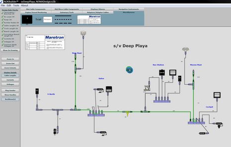
This is a pretty straight forward network (and all Maretron), but Patrick is using connector components in unusual ways. Note how the backbone runs through Multiport Boxes in both the salon and cockpit. There’s nothing wrong with this — the Multiport is, after all, just like three tees screwed together, and N2KBuilder sees the backbone as legitimate. But a Multiport seems to cost more than three Micro Tees do; a Multiport becomes economical when it’s used to reduce drop cable lengths, as at Deep Palya’s nav station (plus it can improve connector access).
Note at far left how Patrick is using a tee to connect two devices to the backbone. I believe that’s fine, as long as no cable run from device to backbone exceeds the 6 meter drop length maximum. That tee in the v-berth area is being used as a multiport, and what’s going on there is not daisy chaining (where data from one device passes through another device). Daisy chaining is supported by two major manufacturers — Simrad and Furuno — but is frowned on by NMEA.
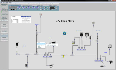
Patrick could easily save some parts expense by simply using inline terminators near each end of his backbone, instead of the tee, stub cable, and terminator shown. Also, when I opened the file in N2KBuilder, I saw a could of unnecessary same gender cable sections, one of which is highlighted below. Also shown in this screen shot is N2KBuilder’s powerful (though still sometimes fluky) “Network Functions” command. I used it to experimentally change the entire Mid size backbone to Micro size cables. I’d already set the input voltage to a very low 10.5 volts, which still supplied the furthest device with more than the N2K 9v minimum. But alarms went off with the change to Micro. N2KBuilder is a lot more than a Visio-like design program.




Another comment on the Deep Playa design: Why go to the trouble of putting the GPS up the mizzen mast? My experience is that modern GPS receivers will usually work fine installed on a cabin top or lifeline rail, or even under a deck.
Airmar’s PB200 wind instument has a built in terminator function, selected by inserting a single (supplied) pin in the connector.
It can also replace the gps antenna and fluxgate compass.
I am going to have to agree with Ben, and here are some of my comments:
Overall: Designing a NMEA2000 takes a little more knowledge about how the products are used. This is almost a great example of how to use the products in the strangest manner possible.
Specfic Comments:
1) Maybe Mr. Walters is European, which makes this moot, but is US custom to draw the bow on the right such that positive X is aft, positive Y is starboard, and postive Z is up, in a right handed coordinate system.
2) As Ben mentioned, don’t use mulitports as part of the backbone. Ultimately, if you do this, part of your backbone will be micro, and voltage drops get weird in using and mid or mini backbone cable.
3) Run up the mast with Mid or mini, with an inline terminator used with the wind sensor (better yet use the PB200, with its dual NMEA2000/NMEA0183 cable, up to 30m, and put the box down low to use the USB software). If I was going to have a second N2K device at the top of the mast, I would T to it, and still leave wind at the end of the backbone with inline terminator.
*PS I modeled the PB200 with a 30m Micro backbone cable to be conservative. I am not sure if the airmar cable is Mid or micro.*
4) If you need stuff forward, T with multiport, if nessicary, or run a loop forward, before going up the mast.
5) This is sort of a thing I learned from reading a number of NMEA2000 design manuals, and can be a real trade off. But doing some sort of iterative process to decide where you put the power input T into the N2K backbone can really reduce your voltage drops. On nearly all sailboats, I have found this is at the base of the mast, right before you go up the mast with your backbone.
6) I see no bulkhead connectors in this design. Are you not going through a single bulkhead?
7) Are maretron products being used for everything. Raymarine, etc. all build great N2K products which could easily be added to the backbone. Remember, this is one of the great things about N2K, they should talk to eachother, and as ben reports, that is getting better and better.
8) It is expensive, and they use alot of power, but 1 DSM250 at each the nav station and the cockpit, that is alot of info for one screen. You may wish to have two or more screens especially in the cockpit.
9) You have two alarms, but you don’t have alot of stuff that alarms. Why not at add an engine monitoring interface, or SIM, or TMP, of DCM, or ACM?
There is one very important design criterion that isn’t well met by Patrick’s design: Understandability. Imagine the proposed setup installed in the bowels of an actual boat. Now imagine opening an access panel, in the salon for example, and trying to figure out what’s backbone and what’s a spur.
I would recommend several changes:
1) Use different color cable for backbone versus spur lines, e.g. blue backbone and grey spurs.
2) Only use Tees to extend the backbone – not multiports
3) When using a Tee, run the backbone through the ‘straight’ part and the spur off of the ‘right angle’ part of the tee – again to improve understandability, not because it matters electrically
4) Attach only one device per Tee – unless that device is a multiport.
Jeff
Ben,
The reason that Airmar and Furuno created the unique pin terminator for the Airmar PB200 and also used in the Furuno GP330 GPS(and coming WS200 Weather Station) is that an inline terminator is physically too long to install and not compatible with many antenna mounts!! This is especially true with angled mounts or flush mount installations.
Using an NMEA2000 inline terminator also subjects the antenna to two physical connections outside the vessel instead of one, for the pin terminator, which doubles the chances for water ingress at the antenna connection point.
It is obvious that the NMEA was too short-sighted in the 6 meter antenna limitation with the existing standards for outside antenna connections where longer cable runs are necessary. This is also the reason why Furuno included a dedicated and powered NMEA2000 Port inside each of their DRS Radar Antennas. Many customers are using this port to add Furuno GPS sensors to their system to save weight and cable runs as either a primary or back-up GPS. The DRS NMEA2000 Port can also be used for the coming WS200 Ultra-Sonic Weather Station.
While the NMEA still frowns on using pass-thru ports on displays for daisy-chaining purposes, Furuno did implement the daisy chaining capability in a clever way in that there is both a male and female connection on the back of each of the Sailing Instrument FI-50 displays. In the unlikely event that a display were to fail in a way that disabled the NMEA2000 ports, the display can easily be bypassed in a few seconds by unscrewing the connetions and simply connecting them together as they are naturally mated.
Furuno Tech
I’m shopping now and a dealer told me that Maretron is claiming that some of the Airmar and Furuno products are not NMEA2000 Certified because of their above mentioned differences.
However, both the dealer and I think the terminator pin and the daisy chaining ideas are really nice features. They reduce the component count and system costs as well.
Bravo Airmar and Furuno!! I learned that there are many types of different connectors for NMEA2000 depending on the manufacturer anyway. The dealer feels that the connection standards are in the toilet because of these issues.
Stan
Patrick here…..
Here is some more info on the design and info on your comments.
1) I’m a total lay person when it comes to this stuff, but I have an extensive background in the computer industry so most of the concepts were pretty straight forward. Most of the NMEA rules I learnt from Panbo.com, Maretron’s doc and some other NMEA reading I’ve done along the way. I think the degree to which I was able to get it right (or pretty close) speaks volumes about the Maretron tool.
2) At the same time I sent the file to Ben @ Panbo, I also sent it to another Ben a Maretron representative I met at the Strictly Sail Pacific show. He and another Maretron employee made most of corrections you all mention, specifcllay the addition of the inline terminators, using blue mid cable for the backbone and only using multiplexers from a T (i.e. the backbone shouldn’t go through the multiplexer, but the tool let’s you do that BUG?)
3) I only drew the network up with Maretron gear because that’s all their tool has in it. It has some “generic” shapes you can use to represent 3rd party gear, I’ve not done any comparisons based on features and price yet. I’m waiting on Ben@Panbo or Practical Sailore to do that for me. I am also considering some analog non-power drawing systems for the fresh water tanks for instance. I just wanted to get a feel for what an “all-in” system woudl look like and what it would cost.
5) Wire in the masts. There seems to be no right answer here. I originally thought it made sense to run the lighter Micro wire as much as possible in the masts (Pearson 424 48′ masthead above waterline) and save a little weight and money by only running the MID cable partially up the mast. The maretron feedback was to do a loop trough the v-berth and then up the main mast. Same thing for the mizzen mast. I am not sure though if either way is “right” or “best”.
The rest of the comments (How will I use the alarms, bulkhead connectors, GPS & Compass, etc.) all reflect the very draft nature of this design.
I hope seeing the process was helpful to all, I’ve found the feedback incredibly helpful. I’ll post more along the way on my own blog (not a businees) so if you care to follow there feel free. http://www.DeepPlaya.com
Thanks again Ben for shairng and everyone else for providing feedback!
Jeff Shukis sent in another interesting N2KBuilder design, with files, and I’ve posted it in a new Forum category created just for this purpose.
https://panbo.com/forum/2009/09/jalanjalan-a-beneteau-oceanis-40.html
(Unfortunately Panbo users can yet upload .n2b or .jpg files into an entry, but I’d be happy to do it myself. Just send files and description to ben.ellison at panbo.com.)
Hey Ben, you should just setup a http:www.drop.io/panbo site and then you don’t have to worry about building the upload stuff into your site.
-p
Great idea, Ben, posting these goodies for comments.
One issue I’m concerned with in the arena of boat wiring, including NMEA, is Lightning, particularly when running wires up the mast.
As lightning strikes to boats are far from uncommon, I’m wondering if anyone has addressed this issue and what are the possibilities of wiping out a whole chain of electronic gear if the strike gets into the wires anywhere along the cable run?
Anecdotes? 😉
Regards,
Merlin
I have strong position on this Merlin.
I studied this topic a long time and asked many questions about how my new boat (in production) would meet various standards and best practices for lightning protection, almost to the point my yard was ready to cancel the order and return my deposit to make me go away. That, and I was buying many more electronics options then they were comfortable with installing.
That didn’t deter me.
I have become convinced however that the best practices can be summed up in
– not creating a ground path to your thru hulls (if they melt the boat sinks)
– not having one of those silly dissapaters on your mast (Ben !), it’s just not fashionable nor helpful.
– do have a generously sized ground strap from your mast to your keel and inspect it, it’s only good for one lightning stike, and thats useful protection for yourself and your crew
– do have spare handheld GPS in one of those metalic protection bags (electronics can be destroyed by a nearby strike without being electrically connected)
– most importantly, for the protection of your electronics especially, have good boat insurance.
Little else works.
Keeping that in mind, leading an NMEA 2000 connection that connects all your electronics directly to the mast could be a good thing. I am told it’s far easier to deal with the insurance company if your equipment is entirely fried vs. having strange unexplained issues.
Thanks, Dan
Have you, or anyone, checked out the system design and components at http://www.marinelightning.com/ ?
Perhaps Ben can get a demo installation and sail back and forth through storms for us?
Seriously, though, catamarans get hit, apparently far more than monohulls, and being at the design stage, I’m looking to do everything practically possible to eliminate or minimize lightning strike damage. To my way of thinking, having lots of insurance is fine, but never needing to USE it is far better, particularly when circumnavigation is involved.
From my research, most older lightning ‘systems’ simply don’t seem that effective. Research in the past decade has brought about a better understanding of the phenomena and the above website *seems* to have a better grasp of the problem than any other I’ve found.
I hope Ben, and others, can chime in on this thread as I see it as a vital survival technology, even in clear weather.
Regards,
Merlin
I’m installing 2 Simnet networks, more or less full-blown on 40+ foot sailboats using mostly Simrad and Simnet. Has anyone built the appropriate Simrad/Simnet descriptions for Maretron’s N2KBuilder and would be willing to share them?