Digital Antenna 992, wideband VHF/AIS antenna with easy cabling
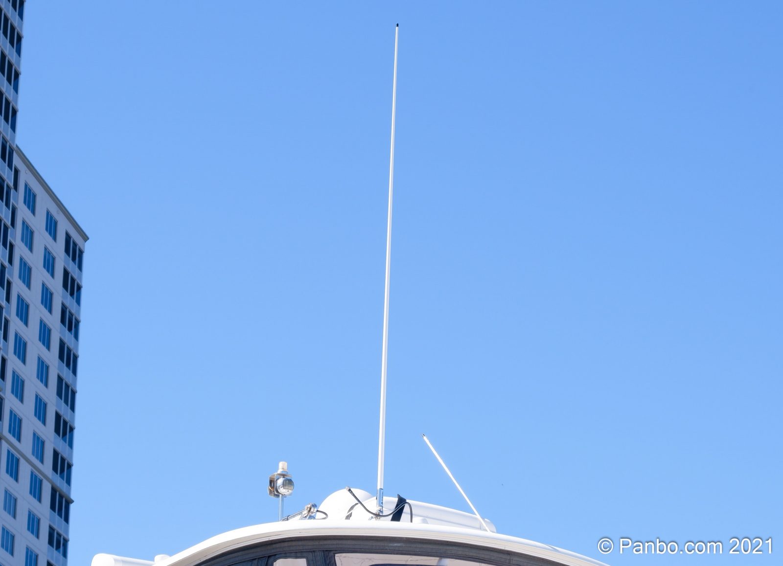
Both Ben Ellison and I have recently installed Vesper’s Cortex VHF Radio, AIS, and boat monitoring system. Cortex uses a single VHF antenna for VHF voice and AIS, which calls out for a wideband antenna that covers both frequency ranges well. Ben E. selected a Shakespeare 6500-WB antenna, and I’ve been testing a Digital Antenna 992 wideband antenna. We don’t have the ability to perform in-depth performance comparisons, but here’s a look at what you should expect from the antennas, and also the installation differences.
The eight-foot Digital Antenna 992 has 6 dB of gain compared to the four-foot Shakepseare 6500-WB‘s 3 dB. The 992 also claims a much wider band than the 6500-WB, covering from 134 to 176 MHz, but only matches the Shakespeare’s claimed 1:5:1 VSWR over VHF voice and AIS frequencies. As Ben E. noted, that’s as good a spec as can be found in marine VHF antennas.
Why wideband?
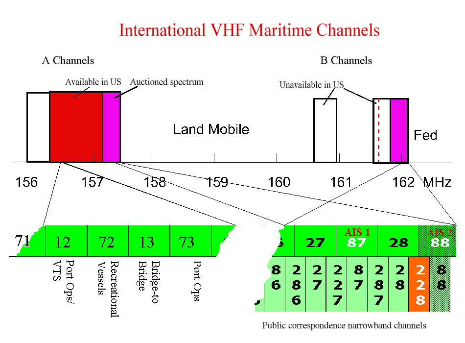
Typically, a boat with a VHF radio separate from its AIS transceiver uses one antenna tuned for VHF voice and one for AIS. Even though VHF/AIS antenna splitters have long been available, separate antennas were generally considered the highest performance option. Before Cortex, even VHF radios with AIS transceivers built-in had two antenna connections.
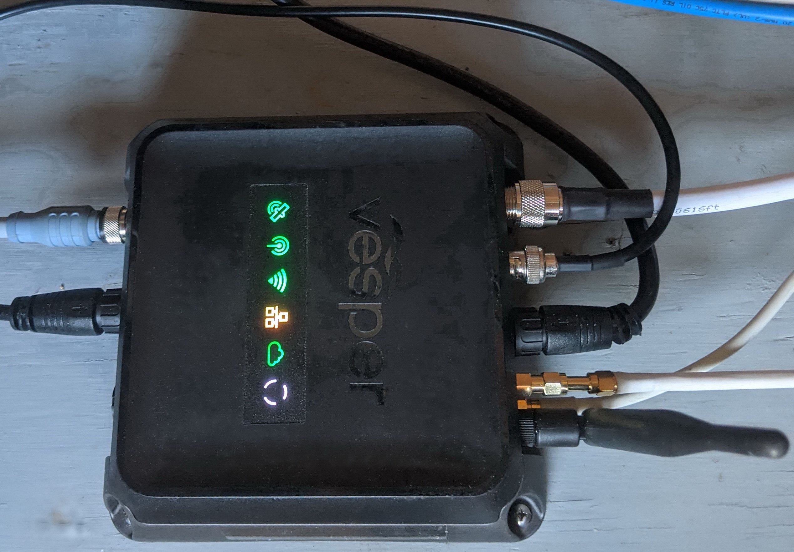
But the software-defined radio used in the Cortex hub handles VHF voice and AIS messages in a highly integrated fashion, and one result is its single antenna connection. Also the conventional wisdom about dual antennas is changing, especially given newer broadband models that perform well from the emergency channels low in marine VHF range through the AIS channels at the high end.
For instance, Digital Antenna’s conventional VHF voice antennas are all centered on channel 16’s frequency of 156.8 MHz with 8MHz coverage. That means they’re tuned to perform best from 152.8 MHz to 160.8 MHz, with AIS frequencies just outside that range. Shakespeare’s Phase III VHF voice antennas are also centered on 156.8 MHz but with 3 MHz of bandwidth, so the AIS frequencies are further outside the best performance range.
But the Digital Antenna 992 and Shakespeare 6500-WB earn their wideband designation by extending performance across both VHF voice transmissions (156 to 157.6 MHz) and AIS transmissions (161.975 and 162.025 MHz). However, that entails some compromise. As John Jones, Digital Antenna’s vice-president of engineering explained, “Optimum antenna performance comes when an antenna is tuned for a single frequency. You can tune the aperture of the antenna on the receive side so you get much less of anything else other than the frequency you’re hunting.” So, by widening the frequency range these antennas are receiving, you’re also increasing the amount of noise that makes its way to the receiver.
So, two antennas are always better, right? Not necessarily. There are myriad other considerations for getting optimal performance out of your radios. One such consideration that’s given me trouble on Have Another Day is antenna separation. Two antennas too close to each other will affect performance, and the closer together, the worse the results. It’s not just antennas you need to worry about; any metal structure, like a mast or support, can reduce the antenna’s performance. So, in many cases, one well placed, properly selected antenna can outperform two compromised antennas.
Antenna gain
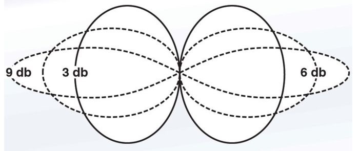
A VHF antenna’s ability to focus RF is measured in gain. Gain is expressed in decibels (dB) on a logarithmic scale. 0 dB represents a 1:1 ratio of power into the antenna and out of the antenna. 3 dB represents a doubling of apparent radiation energy through the antenna, 6 dB is four times the energy, and 9 dB is eight times the energy. But, an antenna is a passive device, so it’s not creating energy out of thin air. Instead, it’s focusing the radio frequency energy flowing through it. The diagram above shows happening. At 0 dB (no gain) the antenna collects energy in a sphere centered on the antenna. As gain increases, the radio signals are focused into a narrower range that increases apparent signal strength but also decreases the coverage pattern. Fisheries Supply has a good primer on marine VHF antennas that discusses marine VHF basics.
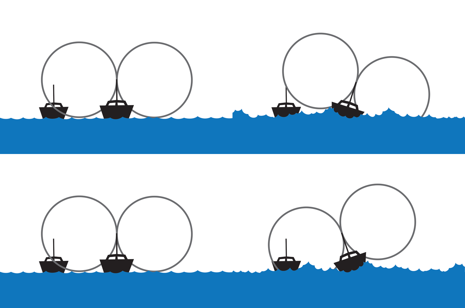
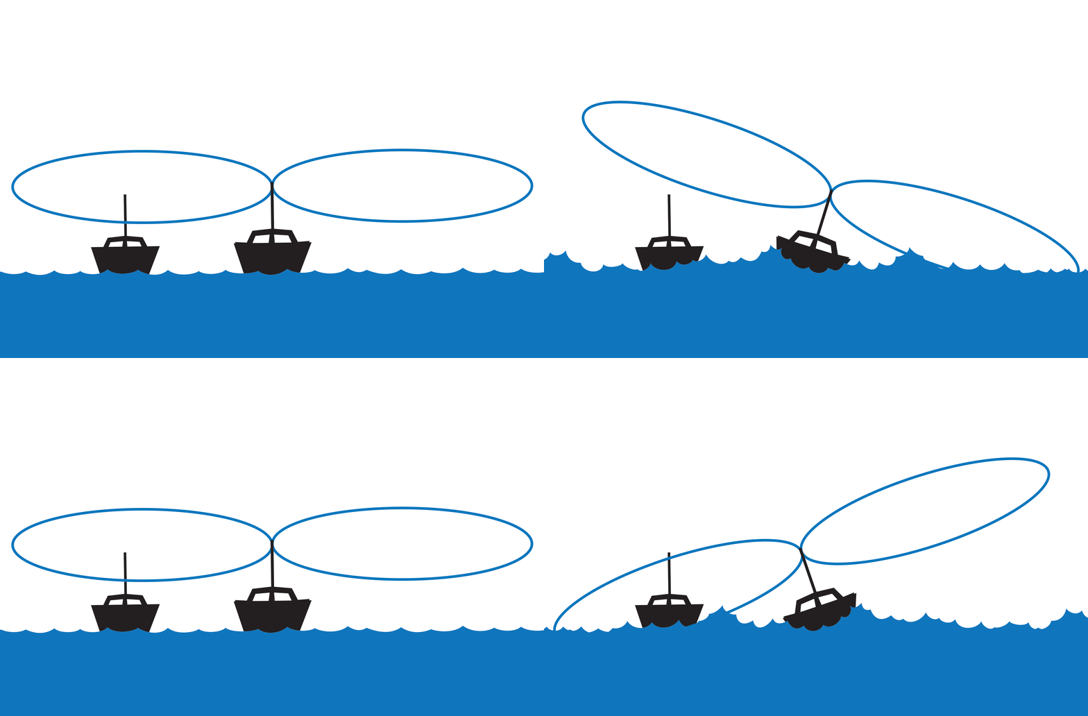
Images courtesy Shakespeare (https://shakespeare-ce.com/marine/antenna-selector/)
As soon as gain is introduced, the coverage sphere begins to get squished, the higher the gain, the more squished. Eventually, the pattern will be a wafer-thin pizza shape, instead of a giant ball. As beamwidth gets narrower, the chances a transmission is missed go up, especially as a boat rolls in a sea-way. Shakespeare’s antenna selection tool illustrates the effects of both gain and antenna height in a way I find easy to understand.
Cabling
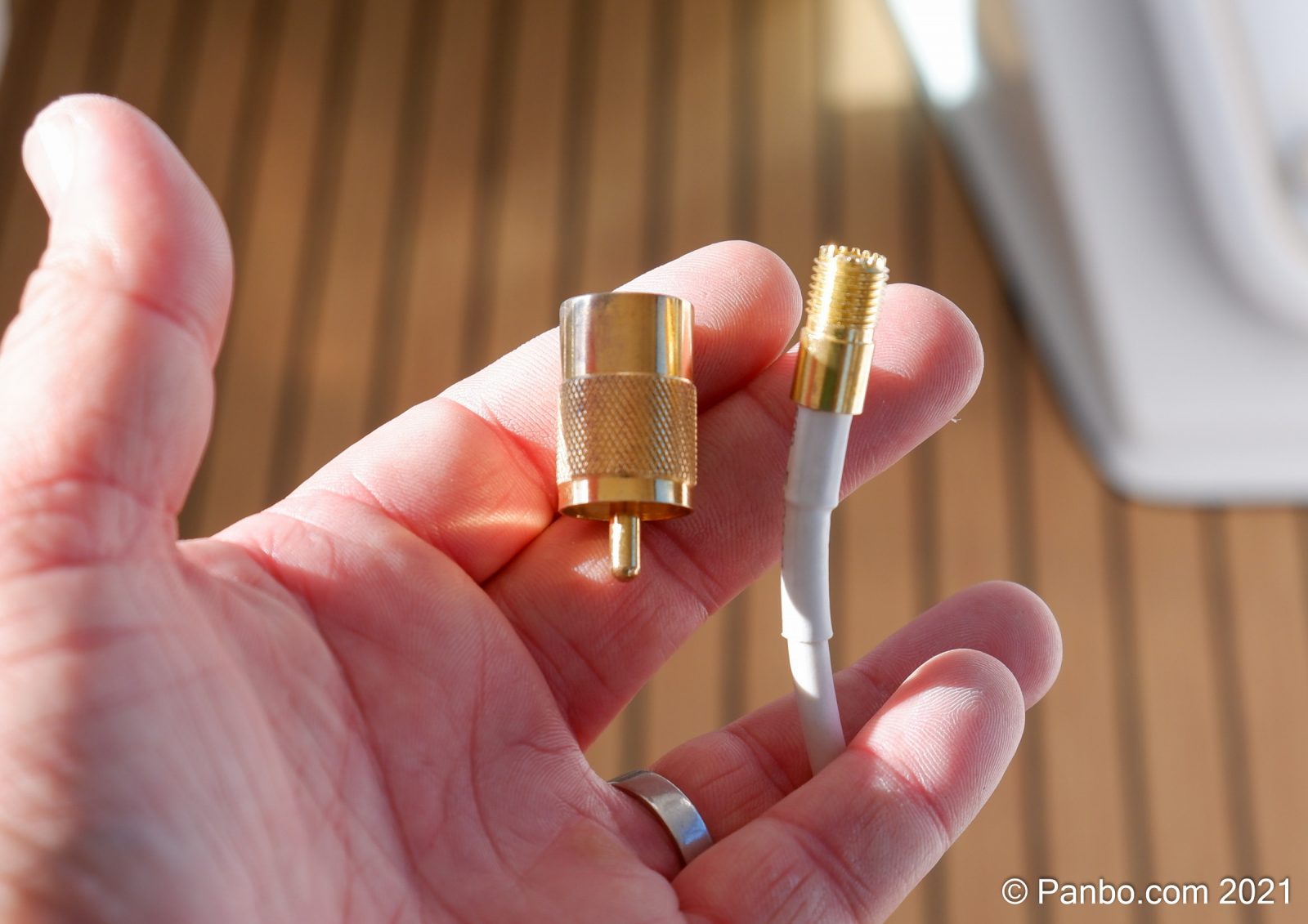
Digital Antenna uses a mini-UHF connector on the end of the cable the 20-foot cable that comes attached to the antenna. The connector is barely larger in diameter than the cable itself so it should be possible to fish it through nearly anywhere the cable fits. A mini-UHF to PL-259 adapter is provided with the antenna, so the entire install can be performed without any soldering but with the confidence of factory-quality terminations. The cable is permanently attached to the antenna, so if you need to replace the antenna you will also have to fish the wire again.
Performance
It’s hard for me to assess the antenna’s performance accurately. Firstly, I’ve done my testing at Legacy Harbour on the Caloosahatchee River in Fort Myers, FL. I’m about 10 miles up a river in the shadow of four large high-rise buildings that have, I think, a negative effect on my VHF performance. Plus, I’ve always been suspicious of the VHF performance on Have Another Day. It has three VHF antennas across the aft edge of the hardtop that are too close together, and it’s seemed anecdotally that other boats have longer AIS receive range. For my testing I’ve laid down all the other antennas near this one.
I have noticed that AIS performance is as good or better than the VHF voice tuned Shakespeare 6225-R Phase III antenna it replaces. Watching targets move up and down the river, I can see them a little further — out to about four nautical miles either way — than with the VHF voice antenna. Plus, with the VHF voice antenna, Cortex consistently threw an antenna VSWR error, but only on AIS transmissions. I suspect that’s because the antenna’s VSWR climbed rapidly outside of its design frequency range. With the 992, I haven’t seen any indications of VSWR trouble.
Final thoughts
The Digital Antenna 992 is a good match to Vesper’s single-antenna VHF/AIS radio. Covering the entire frequency range in a single antenna requires some compromises and purists may prefer two antennas each tuned for a smaller frequency range. But, I believe there’s a good argument for using a single antenna and focusing on optimal placement, good cabling, and clean connections. If you subscribe to that argument, I think the 992 is an excellent choice.




Hi Ben,
I have two “wideband” VHF antennas on Atsa – a Digital 992 installed in 2018 and a Shakespeare HS-2774-1 which I put on in 2014. Since I’m active on 2M amateur radio plus CAP, I needed antennas that could work across the entire band from 138 to 165 MHz. The HS-2774 is definitely wider than the 992 (138-170 vs 145-165), but both cover the Marine band and AIS channels quite well. If either antenna has more than a couple dB of gain over a dipole, I’d be amazed – antenna gain claims should ALWAYS be taken with a an entire bagful of salt!
But they both work – the Shakespeare is significantly heavier and stiffer than the 992, albeit slightly shorter. If you would like a SWR plot of your 992, I could bring my NanoVNA down 🙂
Hartley
S/V Atsa
Of all of this information, the part that is most exciting for me is the connector! I have never been confident in my soldering and assembly of the assemble-yourself connectors, and if this type of fitting is standard on any Digital Antenna, you can be sure I will be switching from my historic use of the Shakespeare antennas. In retrospect, it seems dumb to buy this awesome equipment, and then have to possibly compromise its performance due to my amateur skills of assembly.
Nick, I like the Glomex system even better, similar small connector but you’re not stuck with the cable that the manufacturer embedded in the antenna:
https://panbo.com/glomex-usa-shakespeare-and-the-search-for-better-antenna-cabling-systems/
As you said Ben, they’re using a “FME” connector, which was invented specifically for the purpose of a slim connector that can be installed/snaked easily. As you might imagine, poor installations of connectors costs antenna manufacturers a lot of time, hassle and money 🙂 Glomex puts the male side on the antenna base, so you can adapt to anything you like, or you can use the cable they supply. I think that’s a better system than one where the coax is permanently attached to the antenna – what do you do when the coax gets eaten by the sun (or an errant sheet)?
Pacific aerials is using this system from many years ago.
Pacific aerials is using this system from many years ago
I am helping plan VHF Marine radio land based radio station antenna improvements. The comparison of the Shakesphere and Digital Antenna models and ship installation considerations was very informative. For the land based antenna, we do not experience roll and pitch. However, we do require a much longer antenna cable run over 100 ft from radio to antenna not including any jumpers at the ends. We are looking for an antenna with the highest gain and are looking for a nominal 16 ft antenna with a nominal 9 dB gain around the compass to cover surrounding lakes. Use of two side-by-side mounted antennas is sometimes done, but a single base antenna would eliminate circular coverage affects expected with 2 antennas. We are therefore looking for the optimal Shakesphere or Digital Antenna VHF/AIS Marine Band antenna. Use of a repeater has been considered, so a 100 watt power rating is desirable. We are also looking at using 1 5/8 inch diameter very low loss cable for the long cable run to minimize loss. Your article was very informative in explaining the factors involved in the choice of antennas. We are looking for the higher nominal 9 dB gain 16 ft antenna for base station use. Any make, model and installation recommendations for this application appreciated. Thanks for a good article.
Lloyd, for a 100 foot run, I’ve found that using Heliax bigger than 1/2″ makes little sense in terms of loss vs. dollars. 1 5/8″ Heliax is expensive and the installation is significantly more difficult.
For an antenna, I don’t know what your environment is, but we’ve had good luck with the Decibel (now Commscope) DB-224B – covers 155-165 MHz, a REAL 6 dBd omni coverage (or you can rearrange for 9 dBd offset) and good for high winds (but not serious icing). Tessco.com gets about $850 for them now, but they will last longer and work as well or better than a boat-type fiberglass whip.
I spent 30 years working in the two-way radio industry as both tech and engineer, so I have lots of experience with this sort of thing 🙂
And an additional word about antenna gain. Manufacturers of consumer-level antennas (which is pretty much the Marine market) are acutely aware of the value of claiming a high “dB gain” factor. Unfortunately, the science makes it easy for them to move numbers around.
The lowest gain antenna is the theoretical “isotropic” antenna, which radiates equally in ALL directions (a sphere). Antennas in real life, however, do not do this, they radiate better in some directions than others. One real-world antenna which is commonly used as a reference is a dipole – for the Marine VHF band, this would consist of two 18″ rods, one up and one down from the feed point. The lower rod can also take the form of a tube, and I suspect most have seen some VHF antennas that looked like this. The dipole antenna has a gain of 2.14 dB over the isotropic antenna. It achieves this by not sending power directly up or down, but instead directs it out toward the horizon.
A good way of guesstimating antenna gain for omnidirectional antennas is to examine the vertical size – one dipole length (about 37″) will get you 2.14 dBi (isotropic) or zero dBd (dipole). Doubling this will get you 3 dB more, so a 7′ antenna should have about 5.1 dBi or 3 dBd. Doubling this again to 14′ will add an additional 3 dB, or 8.1 dBi and 6 dBd. Each doubling gains you 3 dB (always assuming omnidirectional coverage). Decibel Products used to sell an antenna with a real 9 dBd gain for VHF – it was about 38-40 feet long, and could only be side-mounted to a tower!
You can see that manufacturers of the “16 foot” VHF antennas are likely rounding up from 8.1 dBi to get their claimed “9 dB” gain figure. The commonly-encountered “38 inch” sailboat antenna (the one with the can or coil at the base) is commonly called a “3 dB gain” – but it’s just an end-fed half wave, equal in every respect to a vertical dipole, and therefore 2.14 dBi or 0 dBd.
You will note that few antenna manufacturers will identify what sort of decibels they’re talking about in their literature :). In the professional field, they generally DO list the reference (usually dBd), and gain figures are usually more reliable.
Rant off… Antenna gains are like anchor stories – ya gotta pay attention to the details 🙂
I’d probably use LMR-600 cable. If you do not need to cover omnidirectionally (you are probably not situated in the center of a lake), perhaps a yagi would provide good coverage in a particular pattern. Be sure to ground your tower and radio equipment together and to electrical ground.
Could we make a dipole from a vhf on top and ais on bottom? Or would the SWR be too high?
Actually, Joe, an actual dipole (made from suitably thick rod or tubing) would probably be plenty broadband to accommodate both VHF comms and AIS, as they really are not all that far apart, frequency-wise.
The common “sailboat” VHF antenna, with its matching “coil” at the base and a thin 3 foot whip is generally wide enough IF the whip is carefully cut to the proper length. I’ve found, though, that the whip is usually cut a bit too long and is resonant at 156 MHz, leaving the 162 MHz AIS a bit high on SWR. Trimming the whip for resonance (lowest SWR) at 159 MHz yields usable SWR for both applications.
Most radome-type (encased in a fiberglass tube) VHF antennas, unfortunately, do not allow you to trim them 🙁 .
Hartley
If Im not running an AIS but just looking for a great antenna for my boat. Is this antenna better for just VHF than the digital 529 antenna?
Funny you ask, Mark, as I recently received info from a cruising friend who has had poor audio and AIS performance with two 992 antennas each supporting a Garmin Cortex. He subsequently installed a 529 which works better, even for AIS. I’m hoping he’ll post what he learned from Digital Antenna, but it definitely sounds like the 529 (or another regular VHF antenna) is better suited to your use.
By the way, I never tried the 992 myself. I’m the other Ben happy with a Shakespeare 6500-WB for Cortex combination VHF/AIS use:
https://panbo.com/searching-for-a-quality-vhf-ais-combo-antenna-shakespeare-6500-wb-found/
Have you ever tried a comparison on which 8′ VHF antenna has a better range and recpetion?
I currently have two shakespeare 5225 xt antenna but one works decent and the other not as good. I used to have digitals on my last boat and they worked great. Thinking about swapping back to digitals. Maybe its how I did my solder and connections but one of them is soldered and the other is a pin connector.