
ABYC Ratifies E-13, their first lithium battery standard

The ABYC has ratified standard E-13 covering the installation of lithium batteries on boats. E-13 replaces TE-13, a technical note that provided a preview of the direction the ABYC was headed with the standard. But, not having an approved standard for lithium battery installs presented some challenges. The main one comes from insurance companies not having an approved standard they could reference. Now that we have a standard let’s look at what it means for new installs and those who have already installed lithium batteries.
I’m not an expert on the many intricacies involved in getting a standard ratified, but I have had the opportunity to discuss the standard with those who are truly experts. To me, E-13 looks like a good start, but I think there are some areas where the standard could require more. I fully recognize the committee had a tough job of getting a standard out for new technology that ensures safety while not making compliance overly onerous. I hope E-13 represents a starting point and now that it is ratified and published, we will have continuing conversation and refinement of the standard.
E-13’s recommendations take effect for systems manufactured or installed after July 31, 2023. So, manufacturers, installers, and boat owners have a year to prepare for the requirements. Also, the standard’s scope lists that it applies to systems of 600-watt hours or greater. For a 12-volt system, that means systems with a capacity of 50 amp-hours or more.
E-13 is a standard for lithium ion batteries. That’s a category that encompasses quite a few chemistries, including lithium cobalt oxide (LiCoO2), lithium manganese oxide (LiMn2O4), lithium iron phosphate (LiFeP04), lithium nickel manganese cobalt oxide (LiNiMnCoO2), lithium nickel cobalt aluminum oxide (LiNiCoAlO2), and lithium titanate (Li4Ti5O12). It certainly makes sense for the standard to encompass the range of potential chemistries, but I firmly believe that of the currently available chemistries, LiFePO4’s safety characteristics make it the only logical choice on recreational boats. As a result, most of this piece will concentrate on how the new standard will impact the installation of LiFePO4.

Much of E-13 requires the batteries be installed, operated, and maintained according to manufacturers’ recommendations. In the case of the higher quality batteries that include thorough documentation and specifications, that seems like a fine recommendation. But, there are lots of lithium batteries available on Ali-Express, Amazon, eBay, and other sites that come with varying amounts of information. Additionally, the information they do include can be of dubious quality.
Physical installation

I’m pleased to see a note in the general requirements section of the document acknowledging that lithium batteries don’t have spillable electrolytes nor do they routinely off-gas. Hence, the electrolyte containment requirements of E-10 may not apply. But, I’m not sure if a note in one standard relieves the requirements of another.
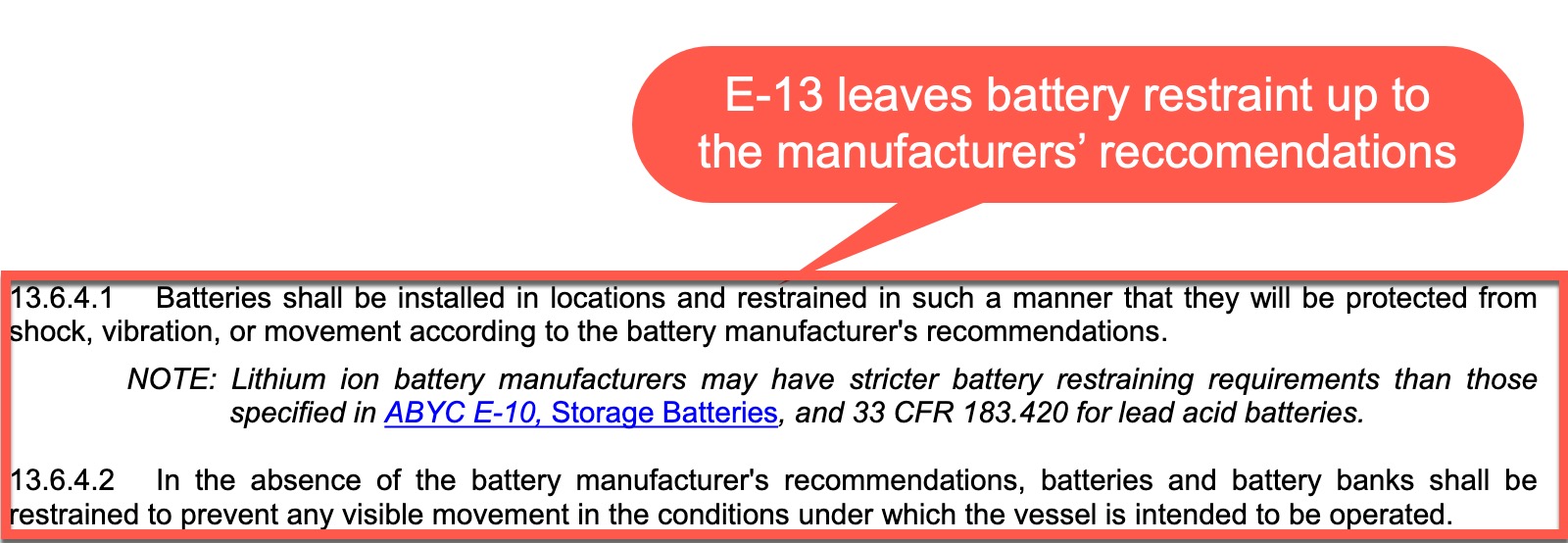
Overall, the standard is highly reliant on the recommendations of battery and equipment manufacturers. Some of these areas make a lot of sense, while others, like battery restraint, don’t.
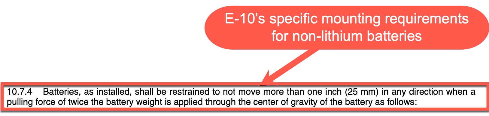
ABYC’s E-10 standard already contains specific requirements for how a battery is to be restrained. I may be missing a nuance here, but I don’t understand why E-10’s requirements weren’t used unless a manufacturer has more specific and demanding specifications.
Edit 9/9/2022 – I’ve been in touch with a representative of the ABYC who clarified that E-13 is more restrictive than E-10’s 1 inch of movement requirement. His point being no visible movement is a higher standard than one inch of movement. For whatever reason, in my first reading, that wasn’t how I interpreted it. With his clarification, I now see how that’s a stricter requirement. But, it also seems more subjective than a specific measurement.
BMS required
I’ve heard anecdotes of lithium batteries being installed on boats without a battery management system (BMS), but I haven’t come across such an installation on the water. As far as I’m concerned, that’s a good thing. Battery management systems ensure the battery is operating within its safe operating envelope (SOE) and disconnect the battery in the event the battery exits its SOE. E-13.7 requires a BMS on all lithium batteries installed on boats.
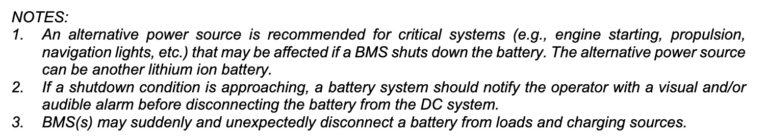
The end of 13.7 contains several notes. My understanding of notes is that they serve as recommendations but don’t carry the same requirements as items in the main body of the standard. Note 1 in the section recommends alternative power sources for critical systems. It’s worth noting, another lithium battery is acceptable as a redundant power source. The second note suggests that BMS should give an audible or visual signal when a disconnect condition is approaching.
I expected the standard would cover external communications in greater depth. An audible signal from a battery deep in a bilge is unlikely to be heard by an operator at the helm. Plus, in many cases, I think communication between the battery and charge sources could be more important than signaling the operator. Ultimately, batteries with external communications via CANBus or similar means can probably do both. I hope that over time the standard will be expanded to help ensure the safest possible operations.
Instruction Manuals

I’m pleased that the standard requires a manual or collateral literature to be provided with the battery. There’s a litany of manufacturers of lithium batteries, and while some provide excellent information, others give the user little more than a flyer with the battery. Those flyers often don’t have enough information about the recommended operational parameters to ensure safe operation.
Section 13.8 requires that manufacturers supply information on cell chemistry and design, safety hazards specific to the battery, safety features, requirements for safe operation (items like charge and discharge limits, temperature limits, and any external equipment needed for safe operation), any requirements for charge sources, serial and parallel connection capabilities and restrictions, and battery restraining requirements. Additionally, the manual must provide information on the effects of external heat and fire, fire suppression requirements (like a specific fire extinguishing medium), and information on hazardous gasses that can be released. Lastly, the product literature should include information on how to recycle the battery.
One thing not yet required that I hope may be required in the future is information on the specific thresholds at which disconnect events occur. I feel this information is key to designing and installing a safe system. As I was writing this entry, I went and looked at many battery manuals and was pleasantly surprised at the comprehensive manual Battle Born now provides with their batteries. It explicitly spells out the voltages at which high and low voltage disconnects occur, the temperatures at which high and low temp disconnects occur, and the parameters around both high current and short circuit disconnect events.
Final thoughts
Overall, I believe LiFePO4 is safer than the lead-acid based batteries we’ve been installing in boats for many decades. LiFePO4 batteries have safety mechanisms in place to shut themselves down if they exit their SOE. Lead Acid batteries don’t. The failures I’ve seen with LiFePO4 batteries are more graceful than the failures with FLA. But, the batteries do store a tremendous amount of energy. Without proper installation and care there is an inherent danger things can wrong with all that energy. Following E-13’s guidance will help ensure safety. I’m also hopeful that E-13’s existence will help with the rocky landscape of insurance companies and lithium batteries on boats.
Postscript
My friend Rod Collins recently wrote an excellent article for Professional Boat Builder detailing an issue with a solar installation that ultimately resulted in a 12-volt nominal battery bank being charged at over 100 volts! The most impressive thing about this failure is that although the batteries swelled, blew their vent caps, and generally were destroyed, there was no fire, smoke, explosion, or thermal runaway. The entire incident is a reminder that failures don’t occur in isolation and that it can be very difficult to predict what will go wrong and how it will effect the other components in a system.


In researching this entry I came across a writeup of an almost 10-year-old test of LiFePO4 cells being short-circuited. It serves as further proof that LiFePO4 cells react in a predictable and with low-volatility, even in dire circumstances.
https://shop.gwl.eu/blog/Tests-and-diagnosis/TEST-The-Winston-LiFePO4-cell-160AH-short-circuit-at-1000Amp-for-13-minutes.html
-Ben S.
I’m glad to see this published standard and I hope that we continue to see a safe and intelligent migration from lead-acid chemistry to lithium-ion in the marine industry.
I think many people underestimate the risks and dangers associated with lead-acid batteries. The toxic lead, the sulfuric acid, the potential for hydrogen generation….
I personally have been involved in three flooded lead-acid catastrophic incidents in my lifetime. Two were explosions and one put me in the hospital with permanent damage to my eyes. The latest incident with a 4D starting battery blew a diamond plate bilge floorboard about 12 feet across the engine room and gave everything a nice coating of acid. Engines, wiring, plumbing… the works.
I’m a LiFePO4 “fanboy”, and like others I have built my own house bank using prismatic cells and a quality BMS. I’m hoping the price-point on prefabricated units continues to drop, and we see more integration of marine-specific features like NMEA 2000 communications.
Unfortunately, I’ve seen multiple lead-acid explosions first hand. I was very fortunate not to suffer any lasting injuries. I definitely share your view that there’s much real danger in lead-acid and a move away from it is definitely good.
-Ben S.
I’m building my own battery from Primatic cells now – the price is still less to DIY and more importantly the space savings will be significant
Ben, does the standard make any mention of requiring protection for the alternator in the event of a disconnect condition? I know most installations add this as a matter of course, but it seems like it ought to be a requirement to avoid ending up with both an unusable battery bank and a blown alternator….
Grant,
It doesn’t. In fact, there’s really no mention of system connectivity in any way. The closest we get is the note suggesting an audible alert for a disconnect event.
-Ben S.
Hmm. Seems like they have some more work to do. These (or any batteries) are not installed in a vacuum – what’s the point of having “boat” standards if they don’t consider their relation to other connected systems?
I think those are fair questions. Over on a Facebook group, I was chided for not asking more questions of ABYC before publishing this entry. I’ve since asked several questions of them but haven’t received any answers from ABYC. I’ll update either the entry or comments if I do hear back on any of those questions.
-Ben S.
I have received some updates from ABYC. I’m seeking a little clarity, but will update the article with some notes shortly.
-Ben S.
A standard, by definition, should stand alone. If you have to ask ABYC for clarification, then that in itself is evidence that the standard is incomplete.
E-13 is a good start, and seems to address a lot of the most common and blatant design and installation problems with lithium batteries. I’m cautiously optimistic that insurers will get on board and accept a surveyor’s comment that “Lithium battery installation is in compliance with ABYC standards” instead of just panicking and saying “Nope”.
I do hope that a few important best practices for lithium systems will make it into the next version, specifically:
– The need for separate disconnect relays for charge sources and loads, i.e. a situation that calls for BMS commanded cutoff of charging sources should not kill power to the VHF and bilge pumps.
– The need for communication between the BMS and the charge source regulators, i.e. if the BMS needs to cut off charging, it should do so by commanding a clean shutdown of the alternator regulator, not by suddenly opening the circuit and letting the alternator cause a huge voltage spike.
Those rule out many of the “Drop-In Replacement” lithium batteries now available, and so I suspect that manufacturer interests may have pushed hard against sound engineering judgment here.
Having been on the ABYC committee working on this (it took a long time!) I can say that things did get watered down quite a bit. This was somewhat under the influence of manufacturers and installers that want to keep things simple and less expensive.
However, no matter what the Standards don’t say, we generally don’t charge lithium batteries with alternators without CANbus integration with compatible alternator regulators. Before such integration existed we would at the very least have a BMS-controlled circuit used to turn off regulators/alternators before the BMS has to cut itself off from the system.
If the alternators are relatively small relative to the battery system, we can still do it that way (simple BMS control circuit, a Balmar regulator, etc.). However for the powerful alternator charging systems that most of our projects need, we nearly always use the Wakespeed AP500/WS500 regulators that integrate with most of the top Li battery BMS’s. Better to prevent a cutoff in the first place, than to relay on a last-minute full charging system cutoff.
Thanks for your insight, Bruce. Great to hear from someone who participated in the process.
I agree that an ideal design wouldn’t have a BMS-controlled battery being charged by an alternator without communications. But, I have also seen quite a few field installations where just that is done. I hope that in the future, the standard will evolve to call for either an alternator protection device or pro-active communications before a shutdown.
-Ben S.
Our position is, whether the Standard evolves or not we simply don’t want uncontrolled cutoffs. And although the APD/APM alternator “protection” (voltage snubbers) devices may save an alternator from burning up in a cutoff, it almost certainly won’t prevent damage to any sensitive electronics that happen to be on the same system when the battery has to check out. So we really don’t depend on those.
On top of a CANbus integrated system, and a backup BMS single-wire alternator regulator power cutoff, we still also typically use a dual-channel system (BMS controls charge and load sides separately). This way, whatever happens on the charge side, if all else fails at least the voltage spike/damage will be limited to the charge side, and isolated from the loads.
With powerful charging systems and Li batteries, better safe than sorry…
Bruce,
I agree with everything you suggest and practice in your builds.
Without meaning to take anything away from your superior design, I’m also cognizant that not every installation of Li batteries will have the same budget. For those boaters with a smaller budget, the design you mention may not be within reach. In those cases, I do believe that something is better than nothing.
-Ben S.
Definitely. And on smaller boats you can just use the existing alternator to starting battery config, and use a B2B charger from the starting batt to charge the house in a safe manner. That is, when fast charging isn’t really needed.
I haven’t hung the LiFePO4 batteries on my big boat yet… still doing an evaluation on my smaller boat that is powered by an outboard (E-Tec).
Configuring the system as Bruce mentioned is what helps me sleep at night. Charging current from the E-Tec goes to the starting battery. From there a VSR (B2B) provides charging current to the lithium house bank. My security is knowing that if the lithium BMS taps-out for any reason, the starting battery will still be there in parallel to keep the E-Tec voltage regulator from seeing a complete disconnect, and to protect my house electronics from being exposed to the transient…
@Bruce thanks for participating here – I’m just catching up in late 2023 and found your comments super helpful.
The idea that the system audibly notifies the user before cutoff worries me, unless it is at the helm. Before you lose power to your autopilot and everything else, do you really want an audible notification from your bilge, engine compartment, or even DC panel causing you to leave the wheel and investigate? Placing the audible notification at every helm in your boat would be better. Better to draw you to the wheel before cutting off major systems in your boat, so you can steer and slow down IMHO
Some upcoming BMS’s to meet the E-13 will have a wire to drive the ground to an external alarm…so installers can add as many alarms as they like of whatever volume (use the feed to drive a relay that can power alarms of too much current for the BMS feed). This would be in addition other likely SOC and voltage alarms by various monitors/etc. that will vary from boat to boat.
Bruce, most (all?) inexpensive BMS systems / Drop In’s are unable to alarm when they fail. It would be a good feature if the BMS would connect to at least a 2nd BMS/battery combination and have the ability to alarm on its behalf. For example, if you have two batteries in parallel, and one has shut down, know that your redundant battery is out of service. I recall Rod C. telling me that this is a common failure mode. As many marine installations can benefit from having two batteries either for redundancy or the need to sometimes support higher currents, do you see this feature coming?
Bruce, every impressive Lithium-Ion system I inspected has the load and supply terminals separate, allowing the batteries to manage the cut-off from load and supply separately, e.g. without accepting charging current they can provide current to the boat. This is a feature missing from lithium Ion drop in’s that have the standard ground and +12 terminal. Is that just how it will be, or do you see this feature (three terminals) being added to drop-in products in the future?
Hi Dan,
I’m curious what lithium-ion batteries on boats you’ve seen with separate discharge and charge terminals? I’ve seen such batteries, but none of the ones I know of for marine applications contain this provision. For example, Mastervolt, Victron, Lithionics, and Battleborn are all, as far as I know two terminal batteries. I’ve certainly seen provisions in the BMS for them to stop accepting charge while allowing discharge, or vice-versa. But that’s done in the FETs on FET controlled BMSes.
I’m also wondering how a load and charge source, like an inverter/charger would be connected.
I had understood Bruce’s comments about dual channel BMS approaches to imply that’s done in the BMS, not via distinct terminals. But, it’s certainly possible I misunderstood.
-Ben S.
Nearly all the Lithionics systems we sell for marine applications use an external, dual-channel BMS or BMS’s (some larger boats like Nordhavns will have 8x large batteries running through 4x BMS’s). It is nearly impossible fit dual contactors (note: contactors, not mosfets!) inside the case of an internal BMS battery. The external dual-channel BMS has a direct connection to the battery (or batteries) however inside the BMS it splits the output across separate contactors so there are two B+ posts on the output the BMS.
Some internal BMS batteries do have the ability to block current in or out (mosfets facing both ways) however that doesn’t help protect external loads from errant charge sources.
Bruce,
For those dual-channel installs, are you spec’ing all single-purpose equipment? So, no inverter/chargers only separate inverters and chargers? Or do you have some dual role equipment on the charge or discharge bus?
You can do separate chargers-inverters, however the products choices are more limited. Besides, inverter-chargers that are rated rated for controlled power supply are fine to install on the load bus, because 1) They’re typically not capable of runaway overvoltage like an alternator. 2) The higher-end units like the Victron Multiplus and Quattros have a control circuit that the BMS can use to direct them to implement a programmed reaction (typically, cut back to a lower “float” voltage). And 3) The most common/likely problem mode with an inverter-charger is inverting down to low voltage.
If “3” happens, a dual-channel system cut off the load side but leave the charge side connected. So instant recharging via alternators is easy, or solar charging can automatically recharge the next day (unattended) and the BMS will reconnect the load bus as the voltage comes back up.
Excellent comment on the compatibility of inverter/chargers with two B+ posts, and yes I had in mind dual sets of mosfets with two B+ posts. Can we expect to see them? Also, would like to hear your ideas Bruce on what innovations you expect to see with E-13 published. Can we expect some more innovation from external BMS vendors to continue and reduce the space and component count of a full systems approach to lithium battery upgrades. With more BMS features, I can imagine a robust two battery Lithium solution could look like one where maybe a 3rd lead acid battery is smartly managed by the BMS in such a way to insulate the installer from managing charging voltages for multiple battery chemistries or externally adding spke protection circuits for alternators and marine electronics. Perhaps done well, a dual lithium battery solution using an existing lead acid (existing starter battery) could get closer to being, if not a dimensionally perfect drop in, an electrical simple drop-in with just two or three additional battery cable runs and an alarm circuit to the helm to give the boat owner the knowledge that (i) battery capacity lost vs (ii) battery charging failure, so they can replan their trip. Your thoughts Bruce?
See reply to Ben below….
The difference is common or separate port bms. Most good ones with active balancing are separate port
One thing you didn’t mention—a new addition that wasn’t in TE-13—is the requirement that batteries or cells be certified to a least one of several battery construction standards published by the IEC, SAE, or UL. That will limit the choice of batteries in an ABYC compliant installation after July 2023. Victron’s batteries, for example, apparently don’t have any of these certifications.
Maybe worth noting that the April/May 2022 issue of Professional Boatbuilder includes a somewhat humorous but scary piece based on TE-13 by marine surveyor Jonathan Klopman. For those without access to ProBoat, it’s also available on Peter Swanson’s interesting “Loose Cannon” website/newsletter, where it garnered many comments:
https://loosecannon.substack.com/p/youre-not-qualified-to-have-li-batteries
A previous ProBoat column about insuring marine Lithium-ion systems by Nigel Calder is also on Loose Cannon, and Klopman seems to encourage insurance companies to be wary. But as best I can tell, there’s only one that demands an extra high premium with Lithium aboard and hopefully the E-13 standard will encourage others to go easy.
Meanwhile my all-Victron LiFePO4 house bank is working well and I’m beginning to feel quite confident about its safety. But given how long it took me to install, I’m still a little chagrined by Klopman lines like “I try to remind myself that these are pleasure boats, not floating monuments to battery systems.”
In reply to Dan above…
I don’t anticipate much in the way of dual B+ output (dual-mosfet) internal BMS batteries. Dual-channel systems will be in the realm of external BMS’s, in order to keep the battery modules as compact as possible. More energy-dense LiFePO4 modules are coming all the time, keep an eye out for those.
Regarding “drop-in” solutions…even system upgrades using Pb batteries for today’s high-load fast-charging systems are not “drop-in” The currents involved require various cabling/fusing bus/etc. upgrades, and often the charging system voltage is upgraded (to 24V or even 48V). And isolated batteries for loads such as starting/thrusters/winches/windlasses/etc. is desirable vs having different chemistries in parallel. Having the separate banks available as emergency switched power in case of a main battery shutoff is a good idea for backup. For instance in case of a lightning strike taking out BMS electronics (along with many other things), etc.
Each system is a design project, tailored to each boat’s needs. Certainly some packages become repeatable over time (oh, how we wish for this!) but we nearly always have to come up with custom optimized solutions.
And, more often than not, much of the existing wiring in many boats is not reusable without worries…
agree. there’s no such thing as ” drop in ” especially true with Li
Ben,
If you get a chance I would get in contact with the ABYC about attending a meeting, next one should be in Jan. I have been involved in the electric PTC for around 10 years now. If you attend a meeting you will get a good idea the process and how it works. It is a balancing act, one thing to keep in mind with batteries is they are trying to leave room as technologies develop.
In this case it’s going to be hard for standards to keep up. 3 years ago lithium installations were pretty rare, now with lower cost batteries on the market from Battle Born, Relion, Renogy, Expion and others, I see them all the time. All of these also are using internal BMS with no external connections. It would be interesting to see insurance data on it but in general I’m not seeing a whole lot of issues dockside or in the online chats.
I would like to reply to Scott Booker’s reply, above (about setting up to charge with an outboard/smaller boat) but it looks like it’s too far down a chain of replies to have a “reply” button. Scott, I don’t know if you will see this but I hope you do.
You said:
… my smaller boat that is powered by an outboard (E-Tec).
…Charging current from the E-Tec goes to the starting battery. From there a VSR (B2B) provides charging current to the lithium house bank. My security is knowing that if the lithium BMS taps-out for any reason, the starting battery will still be there in parallel to keep the E-Tec voltage regulator from seeing a complete disconnect, and to protect my house electronics from being exposed to the transient…
I have a question about the last clause, as your setup sounds similar to what I have. I get how having the lead-acid starting battery in the system protects the outboard’s alternator if the house BMS shuts things down (start batt can soak up power from alternator); but how is that protecting your sensitive electronics? Are they powered from the start bank somehow? (Mine are powered from the house bank so they would be “isolated” from any protective effect of the lead-acid start battery in a house BMS shut down.) I was considering adding one of the Sterling alternator protection devices (which R. Collins has mentioned) not for its intended use but just to protect the house electronics.
Anyway, I’m really interested in how your electronics are protected by the B2B as I can’t quite work out how that would happen.
(Anyone else is welcome to comment too of course.)
Tentime,
I have a single channel BMS. So if the LiFePO4 battery “taps out” my electronics will still see power from the starting battery if the VSR is closed (engine running, starting battery above VSR setting). If I shut off the engine, the starting battery will ultimately sag below VSR voltage.. it will go “open” and my electronics will be shut down. Start the eninge back up…. starting battery ultimately goes above the VSR threshold, and my electronics get power again… even if the BMS is still “tapped out” (dead, fried, angry, ornery).
Bottom line, my electronics won’t see a transient from the E-Tec charging system.. and the E-Tec charging system won’t be presented with a no-load condition if the BMS “taps out”.
Scott,
So glad you saw this and replied. The advantage you described sounds great (obviously presuming you aren’t running your electronics without the engine running – I do that sometimes but the majority of the time the engine is running).
Would you mind saying which VSR you have? I have a Victron Orion 12-12/18 (purposely sized small because my outboard only has a 25 amp “alternator”) and if I understand it correctly (have to admit the manual was a bit confusing to me) the BMS will cut it off if the house bank calls for that. So I was thinking it would not “be there” in that case to let my electronics soak up power from the start battery.
Maybe this is something I’m not understanding about my equipment. Admittedly it required a whole new mindset to install and wire up, and some of the typical practices weren’t practical for an outboard powered boat (for example there is only one wire coming from the outboard that is both for the starter and the charging so you can’t separate those functions).
Anyway, if you have time, would you mind elaborating on which VSR you have and how you have it set up so that it can continue to deliver power after/if you have had a BMS shutdown of your house bank (that normally powers your electronics)?
My fallback was going to be installing a Sterling APD just specifically between the house bank and the fuse block that handles all my electronics.
Thanks,
Tentime
The Orion appears to be a very nice unit, but I have no idea how it responds if the BMS on the LiFePO4 does a disconnect. My experience is with good old-fashioned VSR’s which don’t have a lot of smarts (I run an old West Marine Unit… but it is similar to the current offerings from companies like BEP, etc..)
The Victron is a “smart” device with charging profiles and voltage/current sensing. Traditional VSR’s are little more than contactors/relays that close when starting battery gets above a threshold voltage.. putting the starting and house batteries in parallel….
So the hookup is simple and intuitive. Alternator goes to the starting battery. Positive cable from the starting battery goes to the VSR. Another cable goes from the VSR switched terminal to the house battery positive terminal (BMS +). All electronics connect to that same terminal (and ground). House and starter battery are common-grounded. Done.
I should note that my LiFePO4 battery is typically charged and maintained by a “smart” charger with a LiFePO4 profile that I use when on shore power. The VSR setup only comes into play when I am underway. It can’t/won’t get me to 100% SOC….. but will keep me in the 90’s.
Scott,
I understand this solution works for you and your knowledge and experience. But, what you’re doing comes with some potential pitfalls. I hate to be that guy, but take a look at the notes from the battery bank construction portion of the standard:
The standard is recommending against a setup in which banks are automatically combined without protections. Most issues associated with mixed chemistries come from how failures are handled. For example, if your starting battery experiences a failure, it may accept troublesome amounts of charge current from the LFP battery. Most charge sources (alternator, inverter/charger, battery charger, etc) are self-limited devices, so the risk is smaller.
-Ben S.
Ben,
I agree that both the starting battery and LiFePO4 bank should be fused or otherwise protected. That’s just a solid practice regardless. As an additional “level of protection” the BMS itself (at least most BMS’s that I am familiar with) will either disconnect or limit the charging current… or the discharge current. Giving an additional layer of protection for both the house and starter battery. A device that actually does “current limiting” in lieu of over-current disconnect would certainly be preferred.
I agree that balancing of the LiFePO4 cells or “batteries” in a bank is important. At the “battery level” this is handled by the BMS and/or external cell balancer. In a parallel bank, it’s still all-BMS. A series bank is a different beast and just charging it off of an alternator output (or VSR) probably isn’t prudent.
I personally don’t consider using a VSR in conjunction with a lead-acid battery as a charging source to be a “mixed chemistry bank”. Guess it depends on how you look at it.
Scott,
I’d agree that it depends on how you look at it. My understanding is that the fact that the banks are automatically combined when the engine is running makes them, at least while the engine is running a mixed chemistry bank. As you said, overcurrent protection is indeed just solid practice and should (but often isn’t) be present at all parts of the system.
The one area I think I might disagree a little is your second paragraph:
The thing is, you’ve only got one BMS involved when you have an LFP battery and a LA battery connected. If what’s happening is within range for the LFP battery, its BMS won’t stop anything. If what’s happening in the LA battery isn’t safe, there’s nothing in the system to step in.
That is part of why I believe LFP enjoys an inherent safety advantage over LA. Yes, it comes with more complexity since the battery won’t stay in circuit until it dies, but it also means the battery probably won’t die, and even more probably won’t do so with a bang.
-Ben S.
The Victron Energy argodiode battery isolator is something to consider when mixing battery chemistries. In MarineHowTo the product is used in combination with alternator protection, in a mixed battery chemistry configuration in this example. See the whole article for context
https://marinehowto.com/drop-in-lifepo4-be-an-educated-consumer/
Sorry for the late post but a few comments that could be of value to other latecomers.
I have a very similar setup to Scotts. Works for me but agree w/ Ben that there could be pitfalls. I had planned to have a B2B (Renogy 2X40 or one 60 amp or a 50 amp Kisae DMT1250) with my setup (105 amp internally regulated alternator directly connected to lead 12v starting battery w/ a VSR connection to 280A LFP house battery) but I found, even w/ a low SOC of the LFP, I never drew more than 70-80A from the alternator (I did add a temp sensor to the alternator and so far so good).
I haven’t done extensive testing w/ LFP SOC < 5% but I think I might be alright in general. If I was cruising for weeks/months on end I'd probably upgrade my alternator and regulator and if there were issues with overheating/overcurrent I'd add a B2B and even alternator protection. Not having a B2B means less $ and less gear to fail but perhaps not as turnkey. My internal regulator is adjustable so set at 14.2v it shouldn't trigger the BMS disconnect while still charging to, more or less, 100%. Also I don't see anything wrong with only charging into the 90 as that seems just fine/ideal for LFP. I've disabled the VSR at a high charge rate mimicking BMS disconnect w/o issue.
One last custom config on my end. I use the relay in my BMV-712 battery monitor to enable/disable the VSR. For 1-2 day cruises I never enable it and only charge at the dock saving belt wear, etc. When I charge on shore power I have my original 20A charger (lead profile) connected to the starting battery and I just again use my VSR to link and charge the LFP. This has been working well though not perfect as the charger has gone into float mode once before the LFP was fully topped up.
just be aware that an APD is designed to protect a typical alternator , it does not necessarily protect downstream electronics that remain connected to the alternator during a disconnect load dump event
by the way ISO/TS 23625:2021 is also ratified and will be approved standard for RCD boats . in Europe the RCD has the force of law unlike ABYC
ISO/TS 23625:2021 is very similar to ABYC TE-13 except in places it offers more stringent specifications then TE-13, but both look like they used the same root documents !!
By the way I think too much emphasis is being placed on LVC , a proper lithium should regard , LVC , HVC, over current and over temp as safety events they should never occur in a properly functioning system. Low battery warnings should occur sooner and trigger things like non priority load disconnects. Any monitored system today on a boat starts screaming at you well before the whole system dies.
Hence in my view HVC, LVC should require manual intervention. Nothing , neither load nor charge sources should reconnect automatically .
Hence too much attention is focus on an event that shouldn’t occur.
“Any monitored system today on a boat starts screaming”. Yes, this is true for lead acid, even the chart plotter and instrument displays will scream if enabled. The balmar battery monitor has the feature. For lithium, isn’t the voltage drops much more subtle, and really require the Lithium Ion BMS to offer up the definitive alarm on low battery rather than using low voltage as a leading indicator?
The voltage is so subtle, it is a terrible indicator to know your lithium batteries are at 30% vs 50% remaining capacity. Many people who buy these want to use the capacity between 40% and 50%. My view is that the BMS needs to have the feature built in to alarm on the actual state of discharge on the battery as not a safety event but also an earlier alarm of “hey man, give me some love in the next 30 minutes or so”. for which the BMS knows far better, than a monitoring system looking at LV.
The safety event alarm then comes more in the domain of the lithium batteries coming within minutes of a discharge so low the battery needs to be protected, without which, standard charging sources become unsafe.
Dan,
I like this idea, but here’s the rub I see in practice… Many (most?) of the BMSes I’ve used do a terrible job of tracking SOC. The premium Mastervolt MLIs on Have Another Day do the best job of any of the batteries I’ve tested, but I still don’t fully trust their readings either. The KiloVault HLXes I’m testing on my RV seem to be just as bad as the Overkill Solar BMS I’m using on my home-built battery. So, I think nearly anything tied off of the BMS’ view of SOC would be troublesome.
-Ben S.
Hi Ben,
We find that the Lithionics BMS SOC tracking is about as good as any monitor can be. However, ALL amp hour counting monitors drift off over time. Which makes doing periodic “synchronizing” charging cycles a good idea. If the monitoring has been recently sync’d, then the calculated SOC% (and associated warnings, reserve voltage cutoff, etc.) can be quite accurate.
Bruce,
Do you know what method Lithionics is using for SOC tracking? I’m guessing it’s coulomb counting but that’s a guess.
-Ben S.
Coulomb counting, temperature, aging/health factors, etc. They’ve had a lot of practice. However it can still get lost if not sync’d for too long a time.
The Li3 default RVC is @ 10% SOC, but is programmable. Most installations also have an additional monitor (BMV, etc.) that they program in whatever SOC% or voltage alarms they want.
Anyhow, with an Li3 system… After an RVC, the reserve on the load side can be accessed with a press of the BMS power button, and also the charging side stays connected on RVC anyhow. But, after a full LVC then both charge and load are opened. Pressing the BMS power button after a full LVC closes the charge side for 30sec.
Yes but the bms has to track SOC cause nothing else really is. Whether that’s voltage or coulomb counting or both. You can’t have LvC as a battery low warning.
I don’t know why ABYC requires Lithium batteries to have information about recycling as a requirement to their standard. I wonder if all equipment they rate has similar recycling requirements. With Lithium, their life is likely around 10 years. And many boats sit in marinas, and in those cases, Lithium batteries if properly managed, may last many more years. Policies about recycling will not effect the safety or usability of something in a boat.
Regarding pressing the button to get access to some reserve battery capacity. Is that physically only available on the bms or can a signal lead on the bms be connected to the engine start switch of an engine where turning the switch to an on position and essentially gets that reserve battery capacity available in advance of pressing a start button or continuing to turn the engine key to a starter position, as long as the actions are done within 30 seconds.
Am I to understand the cutoff to protect the reserve capacity is internally done from lv?
There is an optional remote BMS power button, that has an LED backlight that shows when the BMS is on, flashes if there’s an error/HVC/RVC/LVC/Etc. Not need to connect to engine switching at all; if it’s a dual-channel system the engine alternator, solar, etc. remains connected if/when there is an RVC (@ 10% SOC). Simply start the engine to begin recharging. Note that even if unattended, if there is sufficient solar then the system will automatically start recharging when the sun comes up, and eventually automatically turn the load channel back on.
The reason for the RVC (which can be disabled if desired, but that’s not usually recommended) is so that if there is need to cut off loads, the batteries aren’t sitting right at the very bottom of their capacity, which can contribute to shorter battery life if done often. However, the simple press of the button allows accessing the reserve if necessary for an emergency, etc. Or, to allow recharging from inverter-chargers if they happen to be on the load bus (which they usually are).
I’d like to address what I see as a major flaw in the separate charge and discharge bus argument. ABYC and ISO rightly demand that all loads and or charge sources are disconnected on a LVE or HVE.
In my view these are serious safety trip points that should normally never occur. The BMS has no idea WHY a HVE or LVE occurred. Hence it should never automatically leave a charge bus connected or loads connected.
What should happen in a “
Safety first “ system is on HVE LVE , over temp or over current , the battery is completely isolated from all loads and charge sources. No automatic reconnection should occur. A manual inspection of the bank should then be carried out and assuming it’s safe to proceed , then load or charge sources can be “ manually reengaged. “ either by BMS command or by activating suitable manual overrides.
It the safety of the battery remains suspect and it’s state cannot be determined then all loads and charge sources remain disconnected and an emergency backup power source is enabled.
I would be entirely adverse to ABYC or ISO modifying their specs to support automatic BMS reconnections of charge or load buses
The above entry was thinking safety. If you changed the topic, then ignore the following. Turning the engine key (from off to on) and BMS engaging battery, would be manual, not automatic. If the BMS disconnected the load for purposes of low state of charge and kept some power in reserve (a feature of some BMS’s), why not give some juice to start the engine and receive all that alternator output goodness. It also addresses a safety concern. If the BMS just cutoff the power for low state of charge and the boater needs the boat (for safety reasons) to get moving, letting the engine start makes a lot of sense.
Given that many LFP batteries are 0.5 or 1C , bypassing the BMS to start the engine would be dangerous and unwise . Secondly doing so after a LVE event would be doubly unsafe. Most boats have a second dedicated starter battery so that’s remains available. As a backup to that , small dedicated jump start lithium packs, are widely available and will jump start most engines adequately.
Note that a dual channel BMS typically has carefully thought out setpoints for the charge & load channels. For instance, the Lithionics “RVC” function allows the BMS to cut off the load channel at a calculated SOC (typically 10%) rather than wait for the voltage drop that occurs as the LFP batteries near 0% SOC. The charge channel will remain connected. This leaves plenty of power for engine starting, etc. However, most well-designed systems use a separate battery for engine starting, meaning that needing to use that house bank remaining capacity for engine starting would typically only be in an emergency.
Anyhow, with the RVC function, one example situation would be when/if there is an unattended RVC cutoff of the load channel…since the charge channel remains connected, the solar controllers remain powered on. So, once the sun comes up, the solar charging starts automatically and the system can recharge without any manual intervention.
Note that after an RVC, if the voltage continues to fall, at a certain point the BMS will also disconnect the charge channel (which is typically where the system monitoring is powered from) and completely isolate the battery. At which point manual intervention will be required to restart the system.
A similar setup can be configured with Victron systems, utilizing Smart Battery Protect units, along with the BMS ATD (Allow To Discharge) controlling other misc loads/relays/etc, to cut off loads as needed (as per the system design & setup).
I’m not against a BMS controlling charge sources or doing priority load disconnects at lower SOC levels.
But to me these are merely secondary BMS activities. Bonus features if you like. ABYC and it’s near identical ISO equivalent perceives BMS as a primary safety monitor whose job is to disconnect everything from the LI battery as a safety feature.
A BMS doesn’t really know what’s happening it’s simply see a abnormally low voltage or an abnormally high One , or an overcurrent or temperature event. It doesn’t know WHY.
Hence as I said I would be against any concept where on these safety triggers loads or charge sources would be reconnected by the bms without manual intervention , to me , after battery disconnect there must be manual intervention and then and only then can a reconnection strategy recommenced. This may even require the BMS to be bypassed whetecthe fault is the BMS itself. TE-13 is very poor in the area of faulty BMS and a strategy. A strict interpretation would suggest a faulty BMS wound render the whole battery system unusable. Yet the Li bank could be fine.
I strongly believe a simple system with a Li house and LA starting battery should work close to how a LA house and LA starter battery operates for the boat operator. I can see how the capability Bruce describes in a BMS can achieve exactly that. After a load disconnect, either because the SOC drops to 10% while the boat is in use with engine off, or the boat is unused, that the Li house battery can reconnect the load once it receives enough current from the alternator following an engine start or solar panel reconnect. This is not unlike a having a house LA battery with a low voltage disconnect product,
Regarding charger control, E-13 says:
13.6.2.1 Charging sources shall be operated and controlled to meet the charging profile recommendations provided by the battery or cell manufacturer.
So one way or another, the system needs to keep chargers’ operation within the bounds allowed by the battery. A high or low cell voltage, for example, is an excursion outside of the Safe Operating Envelope (SOE) and is not allowed. It also constitutes “Overcharging” based on the E-13 definitions. It’s up to the designer to decide HOW to do this, but it’s a required control. I think in practice to meet this requirement, there must be some sort of control between BMS and chargers, since only the BMS knows individual cell status.