Lost Bens? Nope, we’re in the lithium mines, finding gold!
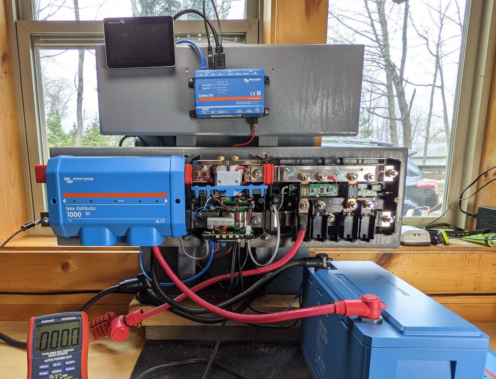
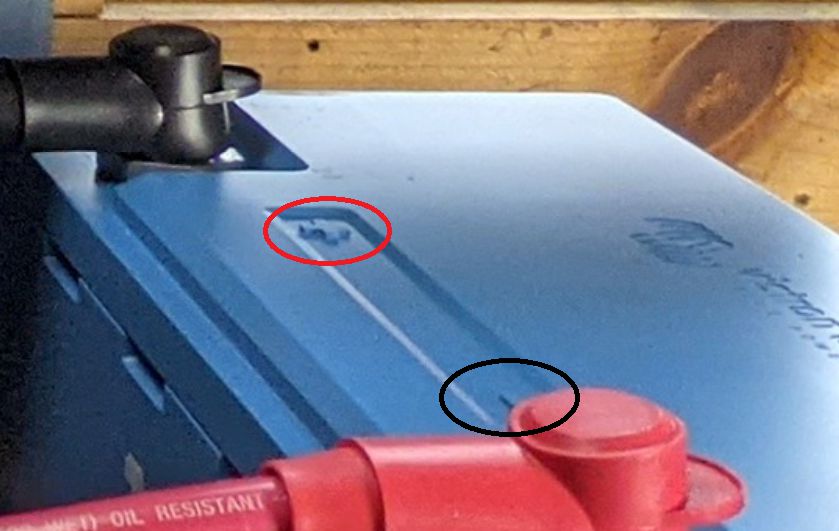
The caption is serious, because right in front of your eyes is the most basic — and possibly dangerous — mistake anyone could make while setting up and bench testing a fully integrated lithium-powered marine electric power system. And it’s a mistake I made even though it was truly right in front of my eyes during the many hours I spent trying to figure out why Victron’s brand new and quite amazing Lynx Smart BMS would not power up. So if you didn’t spot the problem immediately, please take another look before reading the very polite way that VE USA’s national sales manager Rich Shea answered the same question:
I hate to say this, Ben, but from the photo it looks like you have positive and negative reversed on the battery. Assuming you are following red+/black- cable color convention?
Reading that email — along with the zoomed-in crop that Rich attached — nearly caused me to fall out of the chair in my chiropractor’s treatment room (where working in an “engine room” that is definitely not a room can get you). But I tried to give my replies a positive spin:
OMG! So embarrassing, but simple to fix. Thanks
{Then shortly thereafter, once I got the Smart BMS running back in the lab, no damage obvious… }
And with correct polarity, the BMS seems to be working fine 😉
I’d like to pretend this never happened, but the Lynx Smart did survive a test I never would have attempted otherwise.
In truth, I feared that I’d bricked a wildly innovative product so new that they shipped it directly from Holland even though Victron’s U.S. warehouse is somehow just down the road. (Well, actually I’ve learned that there are now three warehouses around the country, but the U.S. HQ is still here in Thomaston, and apparently the very large Rockland warehouse needs to be expanded.)
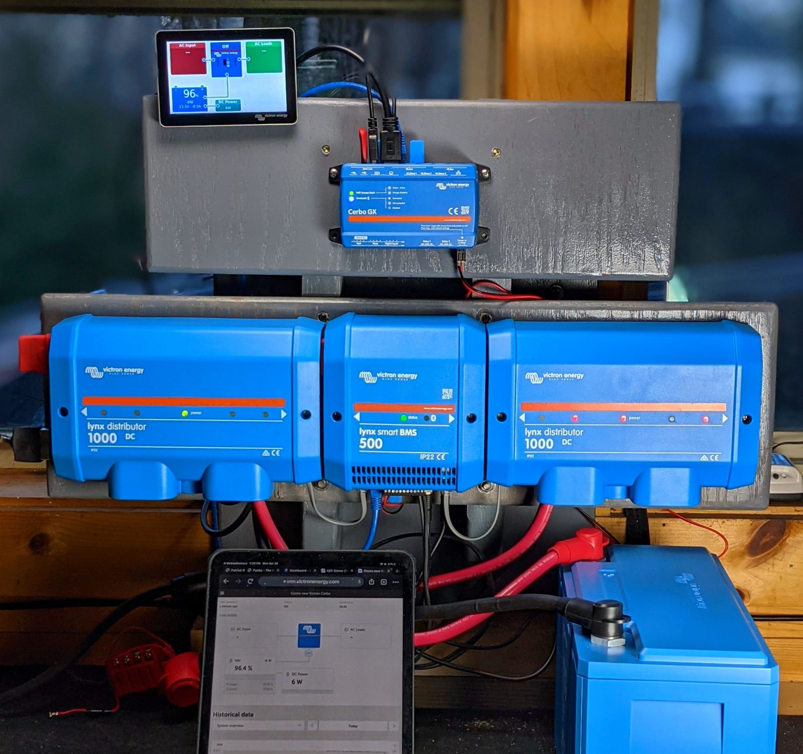
Moreover, as this bench test expanded well beyond any I’ve done before, I made more dumbass mistakes that further tested the growing array of Victron electronics in ways that shouldn’t happen. Including 120v AC mistakes that blew shop fuses, in one case beyond a simple reset. But all the tiny processors and typically delicate whatnot inside the blue boxes seemed to take it all in stride, usually just responding with visual and/or audible alarms in multiple places, including the phone in my pocket and the VRM site open in my office.
There are two points to this tale: How did I make those mistakes, and what does this have to do with the long pause in Panbo entries? My conjecture on the first: Aside from old age befuddlement, I got so focused on all that’s new to me in these photos that I became blind to things I learned when I was about 10. Watch out for that, especially around unusually powerful boat batteries (and, yes, I’ve determined that personal embarrassment is a fair trade for a possibly valuable story).
Answer #2: It’s spring in Maine, Covid spring too, and Ben Stein is even busier with lithium boat battery projects than I am. But patience, please, because we are learning a lot that we plan to share. Besides, I’ve got more techy sexy pictures to show you right now.
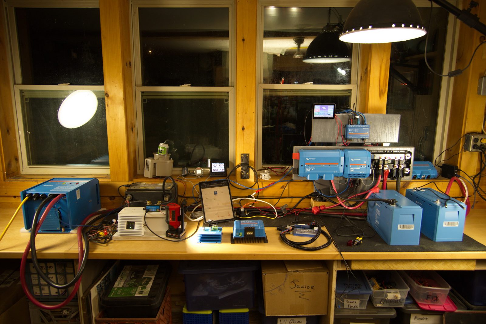
So this is the state of the bench as of yesterday evening. And how about that custom gray 3D Lynx rack (currently the Cerbo’s too)? I’ve already half drafted a whys and hows entry regarding its future value in Gizmo’s “engine space.” Also, as large as that Lynx combo looks, I’ve already removed a heavy bag of terminal blocks, shunts, fuses and so forth that it will replace.
That’s because you’re looking at the first BMS I know of that also positions a 500 amp shunt and a safety contactor right in between an individually fused battery busbar and up to three fused distribution/charging busbars. In fact, they’re all bolted together, though you could use cables, and all the fuses are monitored and can be custom named. And the 1,000 amp rated Distributors will very likely be joined with a 1,000 amp Lynx BMS model eventually, and all are designed for 12, 24, or 48 volts.
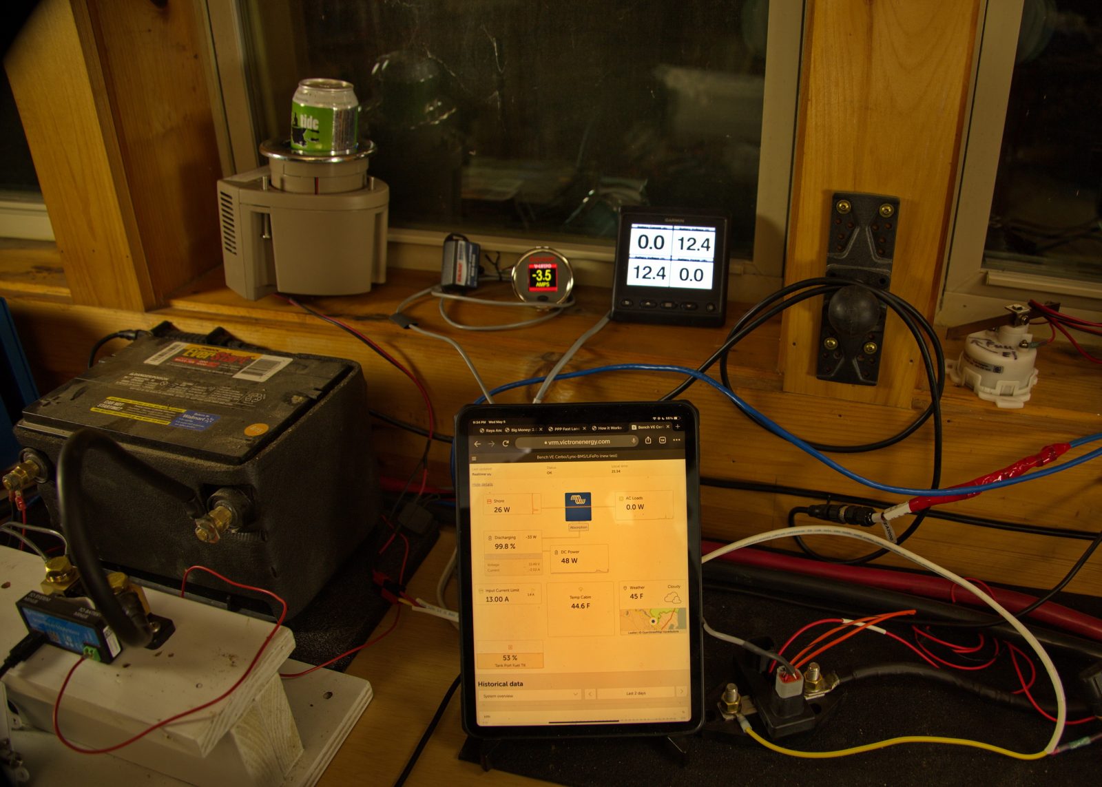
I was hoping to get the trusty old Garmin GMI 20 to simultaneously show the Voltage and Current for both the new Smart Lithium house bank and the simulated starter bank — note the Victron SmartShunt at left — and it actually does if you could see the video. Good enough, as I’m confident from prior Venus GX experience that at least the Maretron and Simrad displays on the boat will be able to show a lot of the NMEA 2000 data streaming from the Cerbo, custom labels included.
Meanwhile the actual load on the LiFePo — cooling one can of beer — is neatly shown by the Balmar SG200 gauge thanks to their SmartShunt, seen to the right. A third shunt, aka belt and suspenders lithium battery monitoring, was not in the plan, until I called Balmar about how to protect Gizmo’s main alternator using my 612, since part of this whole deal is allowing some software to completely shut down the lithium bank if it sees fit (though in this case, even the batteries are crazy “smart”).
Finally, testing the Cerbo with that old white tank sender has me about 90% sure that I can remove the CZone module that’s been bridging all four of Gizmo’s impedance-based Wema sensors to NMEA 2000, with no cons and several pros. The Cerbo’s four temp inputs also seem much more capable than when I first tried these seemingly extra goodies on the Venus.
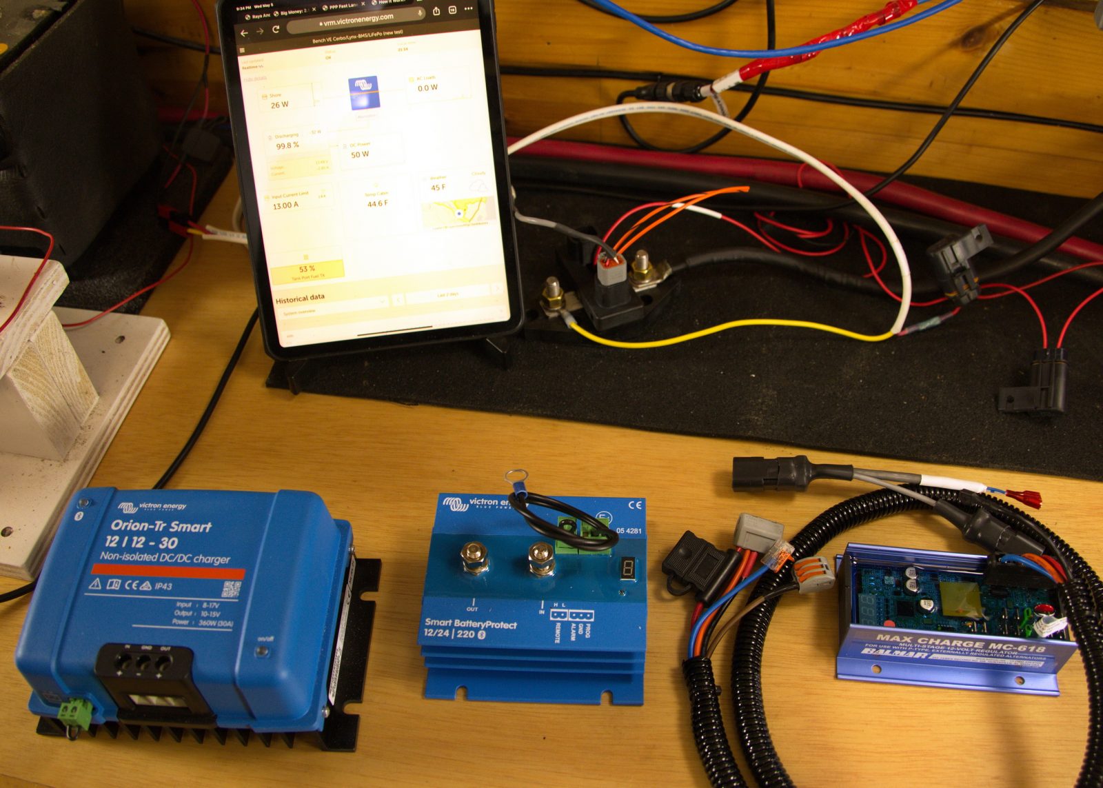
But just setting up the test bench is not yet done. Of particular interest is that almost-out-of-beta Balmar MC-618 regulator. Aside from several improvements on the venerable 612 — some of them oriented to lithium systems (they’re hot, on boats, in vans, and elsewhere) — it can network with the SG200. And that means that I’ll be able to see what the main alternator is up to, either on the bright little color gauge or via Balmar’s Bluetooth app. Plus — praise the Lord, Hallelujah! — I will also be able to program and fine-tune the 618 on those same interfaces, instead of using their still-included, yet long infamous, magnet tipped screwdriver. If I understand what’s going on correctly.
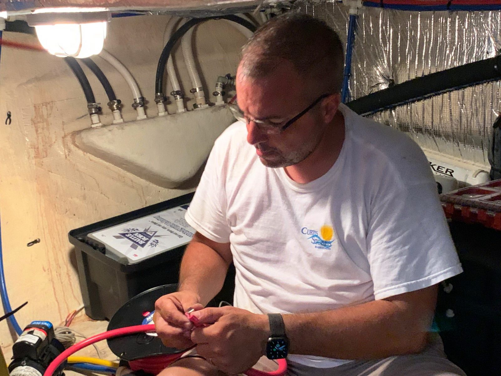
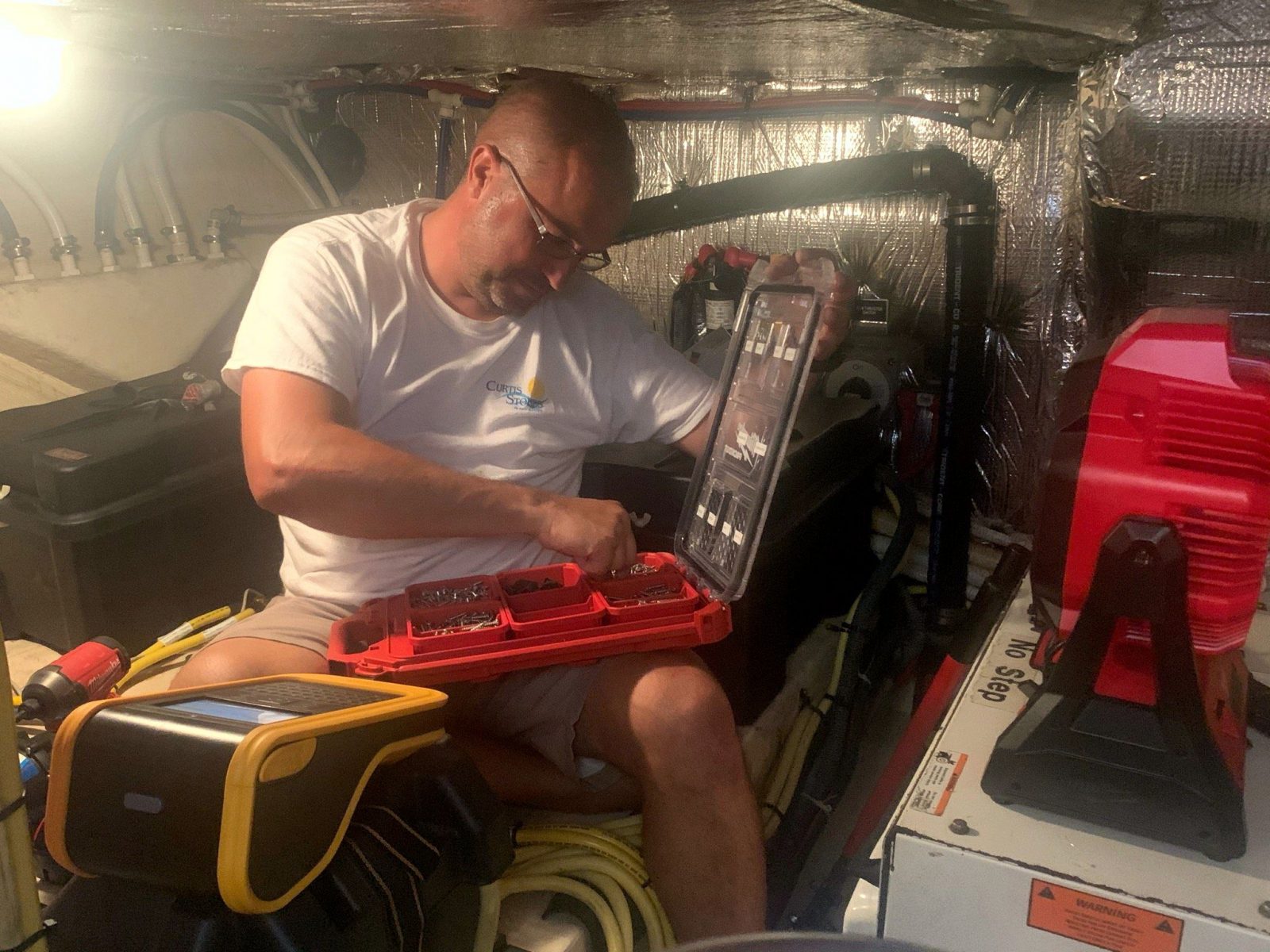
Meanwhile, the only contact I had with Ben Stein last week was when he called from this boat cave for some quick Victron tech support. No lie. I tried, but he was in hurry, hoping to soon test this new system alongside his recent all-Mastervolt lithium install. At least he inspired this entry’s headline, the “gold” being valuable future information for readers (and ultra-modern power systems for long testing on our own boats).
Moreover, I’m pleased to point out that I’ve almost completed a Panbo entry that’s quite light on the excruciating tech details and relevant links. Can I get another Hallelujah!? But the excruciating detail will come, though not because I think this area is suitable for DIY installation. In fact, wise readers should even be careful of trusted boatyards, in my opinion, unless some of the crew are, say, already also part of Victron’s vast global network of trained pros, or Mastervolt’s. But I also believe that many wise readers want to know a lot about systems like these before they make the significant investment and then go to sea with them.
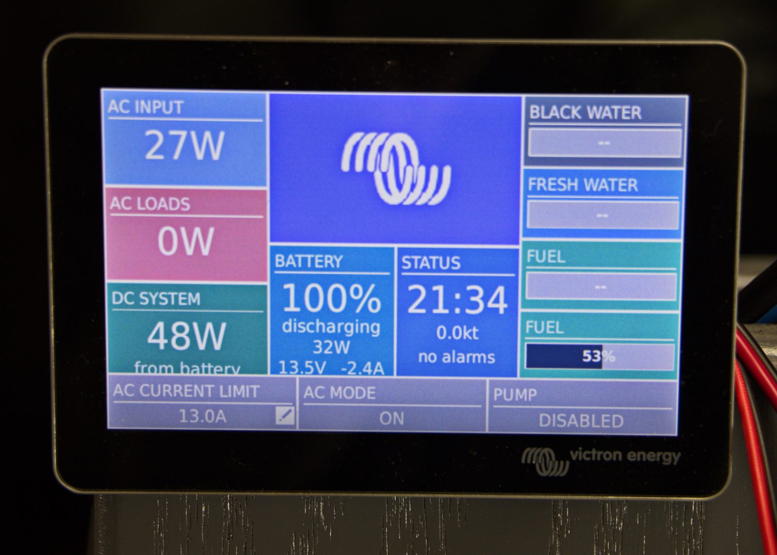
Also, you too can monitor the bench testing, usually in real-time, thanks to the public share pages that are part of my new VRM installation.
And just one more thing. If you’ve already been zooming around the hi-res versions of these photos (and sorry about the limitations, but please take them up with our webmaster, aka Young Ben); or if you’re about to dig into the very fresh details of the Lynx Smart BMS or the MC-618 regulator; or even if you just enjoy puzzles or the embarrassments of old boat guys, check out this early draft diagram of Gizmo’s future power system (a 5mb PDF). I only fully appreciated the value of Victron’s many ultra hi-res sample system PDFs when I hacked one up to make my own. And mine includes a cable error that has so far gone unnoticed even by some Victron developers (I think, or they’ve been too busy to look). Can you find it?






I’m going to take a punt you’ve got the negative distribution bus bar on the wrong side of the BMS/shunt. Am I right? 😉
Right, so that those loads wouldn’t pass through the BMS shunt. Battery monitoring would obviously suffer, but I can only guess at how the system’s remarkable overall intelligence would suffer. For those not already familiar, see Victron DVCC, which is shown as “Forced On” by this Cerbo setup. I only vaguely understand, but I think its why the Multi seems to have programmed itself and maybe why the steady Absorption status looks to me like a very precise float (13.5V 0.1A at this very minute):
https://www.victronenergy.com/media/pg/CCGX/en/dvcc—distributed-voltage-and-current-control.html
However, I do consider that spot –“Scott’s Spot”? — good for the negative cable running from the starter bank, which shouldn’t be included in the house bank monitoring, and in Gizmo’s case will have its own SmartShunt anyway. Am I missing something?
You got me thinking, so I went back and looked at one of the example diagrams Victron has on the Smart BMS site: https://www.victronenergy.com/upload/documents/Quattro-5KW-230VAC-24VDC-600-800Ah-Li-Lynx-Smart-BMS-&-distributors-Cerbo-GX-touch-generator-MPPT-Orion-Tr-Smarts.pdf
Looking at that diagram, the whole starter circuit is on the right hand side of the system, negatives and all, which makes sense, the shunt won’t detect any current through the starter loop since it closes outside the shunt.
Actually, going back to Ben E’s diagram, I think having the whole neg bus bar on the left side may be doubly bad. Going through the parts of the system, you have current returning to the LiFePo battery will be measured by the shunt (good), current returning to the charge controller(s) (bad, eg a solar controller providing enough power to run the inverter without drawing off the battery), and current returning to the starter battery also measured (bad, eg a battery-to-battery charger charging the starter from the LiFePo). So, yah, I think everything that ISN’T the LiFePo needs to be on the right, and only the LiFePo on the left, and you should be ok.
Unfortunately ONLY measuring the LiFePo battery via the shunt is important, because from what I recollect most if not all BMS’s use ‘dead reckoning’ for SOC. Afterall, there is that whole calibration routine with a BMV to get an accurate capacity number to then type in so that the SOC can be calculated from then on. I could go into BMS theory (again, what I remember of it) but it’s lengthy and I’ll only subject people to it if they ask 😉
I’m not an electrical engineer, but I play one on TV 😉 In all seriousness, I’m truly not an expert; anyone please feel free to correct me if I goof.
Perhaps to more directly answer the question of ‘well where should my negative’s tie together between the house and the start battery’ which may have been more of what you were getting at Ben E, I’m not so sure. At first I thought ‘well the contactor could separate when the BMS panics’ but I’m pretty sure the Contactor is only on the positive, not the negative as well. I’m more inclined to tie the negatives together ‘in front’ of the shunt, because that way, the ONLY current that the shunt can be measuring is the curent into and out of the battery it monitors. So I guess with your two shunt system, Ben E, that would be something like this:
Start Neg —shunt—————————————–(or)——
|| (or) ||
House Bat Neg —Distro(Neg)—BMS(Neg)—Distro(neg)——
My Opinion. Other brands are available.
I’m super close to ordering a starting Cerbo setup for my boat – and I notice you have a Color Control GX – but you appear to be doing everything from your iPad. How useful is that Color Control GX? I cannot find ANY documentation on how that device can be configured – is it basically just a panel with that default view shown?
Keith please check Panbo Cerbo entry.
Hi Ben – you mean this comment? “I didn’t get to try the GX Touch 50 at METS but I’m very familiar with that animated and informative main screen, and how a user can drill down to further power detail (and many settings)” So…have you found any of that documented?
Sorry Keith, I only meant the Touch 50 itself. The screen sure looks like the CCGX, just like all the “remote consoles” a GX owner or installer/technician/consultant can call up via various channels.
But I think that comparisons of Cerbo & Touch 50 pairing versus the all-in-one CCGX is the story of Victron’s relentless development cycles (led right from the top). Not to mention the tremendous bang for the buck, even though I’m pretty sure that the CCGX still feels cutting edge and more than satisfactory on many boats.
BINGO, Scott. If you mean the blue cable going to the left end of the left Distributor (quite tired here, and headed offline)
FYI all, The left Distributor is deemed “A” and then you use an easily missed dipswitch pair (ahem) to tag the first right Distributor as “B” and, bada bing, it also shows up in Victron Connect, ready for you to name the mega fuses.
The developers seem a bit apologetic that the fuse states do not show up on the Cerbo and beyond, yet, but they’re on the VC Status screen and I suspect that most any fumble-putz can simulate a situation where they’ll get a semi-urgent notification that goes something like “Orion charger fuse blown!”
I win, I guess 😉
Very excited to see a ‘new’ Lynx system out there now. The Lync family seemed discontinued for a stretch there, and the VE.Bus BMS ‘substitute’ seemed a bit dumb because it REQUIRED the DMC 200A GX IF you wanted to control your charger shore power draw (eg lower demand because you keep tripping the breaker) rather than using the Cerbo/etc control interface (which you can use with ANY other battery setup). The VE.Bus BMS seems to be a holdover for the VE.Bus equipment/day, and in general I think Victron is moving away from that to VE.CAN instead, but that’s a slow process with their history and install base.
I’m much more ‘happy and comfortable’ with Lithium systems when there’s a ‘system BMS’ that tells the devices it’s attached to how and what to charge (tells charge devices what volts/currents it wants). The ‘drop in’ batteries make me nervous when a ‘silent partner’ gets to decide to (randomly) disconnect your battery bank, especially when you run batteries in series for 24v/48v systems.
One small potential gotcha Ben that I was reminded of looking at your diagram is it looks like you may be using the ‘spare battery charging terminal’ in the multiplus. It takes a bit of digging in the documentation, but if I remember correctly that terminal is just a current (and direction) limited feed from the primary battery charge circuit, so that battery can/should/will see the voltages of your primary battery. Given this is a lithium system, I’m assuming primary battery voltages will be higher than LA and you may run the risk of overcharging the battery connected to the ‘spare’ charge circuit. I’m not saying you’re wrong with what you’ve got or that I’ve properly done the math on all this, but this was one of those ‘gotchas’ that I wrote down in my notes when I was reading through the Victron manuals (along with the DMC note at the top) and I thought I would pass it along.
Yes, you are a winner, Scott, and quick too. While I wake up only to learn that I’m a fumble-putz. So it goes. Actually, if you are not the sort to call a good baseball cap a “dad hat”, I do have a prize for you. I just need USPS mailing address.
Thanks again, Scott. I suspect that your last paragraph is a very valid concern. I believe Victron calls it a “trickle charge” for exactly the reason you state, current limited to something like 2-4A and same voltage as what’s needed by the main battery bank. I had wondered about it, and it’s no big deal on Gizmo either way, used or not, except maybe during winter storage. But now on the list of things to explore.
I see that Ben E. spied my fancy new Dymo XTL500 labeler. It’s an expensive little device with equally expensive labels, but boy is it a joy to use. I’ll be writing it up soon but for now I can tell you that the flexibility of being able to generate anything from cable wrap labels for tiny wires to 2-inch tall warning labels for electrical panels is a real luxury.
-Ben S.
Well, I accept full responsibility for getting to here: I am jealous of a young geek with a Dymo XTL500.
But during my lithium process, I have finally learned how to make some fairly good install use of a Brother QL-810W and a newly discovered roll of continuous film labels. I find myself caring about Gizmo’s next owner — while also cursing the guy who did all the quickie installs over recent years (who was me) — but good enough.
Man, I’m glad to see I’m not the only fumble-putz out there that has done that! On a related note, where is the ABYC-required fuse within 8″ (?) of the battery? 🙂
Thank you so much, Hartley. Now I aspire to “fumble-putz fadiddler” or even the role of “fadiddling fumble-putz”
ABYC?
Hey, I can tell you’re having waaay too much fun with that already..
ABYC = “American Boat and Yacht Council”. I’m way too cheap to buy a set, but I’m told their standard for house batteries is that there has to be a fuse within a short distance of the battery itself to protect against the “dropped wrench” hazard. I know I’ve seen Rod Collins talk about them, but a quick search of his site didn’t turn anything up. 🙁
I will certainly look into this, and I’ll add that some of the people on ABYC’s longstanding lithium committee really know their stuff, in the view of this fumble-putz (I can’t control it, Hartley, and you’re to blame).
But Victron knows it stuff too, and I’ve seen no mention of additional battery fusing upstream of the monitored mega fuses in Distributor A, nor maximum cable lengths from there to the battery. Although they are quite adamant about how all the positive ones (RED!) should be the same length, ditto for the (BLACK!) negatives.
PS Check this out, and apologies in advance any reputational or legal consequences:
https://panbo.com/user/ben+ellison/
Anyway, I found this: http://assets.bluesea.com/files/resources/reference/2010_ABYCexcerpts.pdf and 11.10.1.1.1 is what I’m talking about. I don’t know how old that extract is, its entirely possible they’ve changed since then.
I’ve always tried to own copies of Standards that applied to what I’m doing (I bought NECs every few years for a looong time!), but I just can’t get excited enough to buy into the ABYC Standards because I own a boat. If I was making a living doing this stuff, I sure would, though.
Edit to add: I am truly pleased you found my description of our (possibly age-related?) condition so motivational!
Actually, I began noticing a looong time ago that if I wasn’t 100% paying attention when hooking stuff up that I had a tendency to put black to red (or white) quite often — sometimes with startling results – so I got in the habit of forcing myself to **pay attention** during such process’ – and I also keep plenty of spare fuses on hand 🙂
OK, a little preview thanks to the developer Slack channel Victron kindly invited me to join: There’s an interesting update to the Smart Lithiums that I might see in VC soon, or maybe even VRM because Victron has supported remote updates, with rollback possible on the GX series, for quite a while. Even worked fine yesterday on the new MultiPlus.
Meanwhile, it took me two weeks before I realized that I didn’t have to hook up a Smart Lithiium to see the “smarts” — so I walked out to my driveway and opened Victron Connect on my phone. Sure enough, there were the three batteries still heavily boxed up in the back of my car, shipped from I-don’t-know-where via the Atlanta warehouse to Rockland. “Ready for action, boss” was the main message, along with cell voltages and bat temp. One was a single firmware version behind, indicated by an ! icon, and so I did the update while also checking out our mailbox.
Damn! Ben! You write real gud! Hallelujah!
Geezum crow, Doug! That’s the nicest spelling correction I’ve ever received. Just took me a while to get cause sometimes I’m numb as a hake, Praise the Lord!
Hartley, you are correct and this requirement is pretty well established among the installer community in my experience – although for bench-test purposes, perhaps not directly applicable. The requirement is actually not as restrictive as one might think, as enclosing the conductor in a “sheath” gives you up to six feet of room to install a fuse. It’s also not specific to any given battery type…
Hi Grant, yes, Ben’s bench (besides being entirely too neat & clean) is not a vessel, so the standard doesn’t apply 🙂 And that “sheath” is not something special – those flimsy (& annoying) split-loom plastic covers all over your car’s engine compartment qualify. The sheath is just there to show you if something is trying to impinge on the cable itself – a warning layer, so to speak.
My personal preference is to put a big fuse as close to the battery as I can – for a small vessel & battery, the fused lugs that Blue Sea sells look like the right stuff.
Thanks Hartley, and yes, I understand that split loom qualifies as a sheath – although I make a point to use the “marine-grade” type that at least have some flame retardant properties, as opposed to the hardware store variety:
https://www.delcity.net/store/3/8%22-Flame-Retardant-Loom/p_811450.h_811472.r_IF1003?mkwid=s&crid=506797160389&mp_kw=&mp_mt=&gclid=Cj0KCQjwytOEBhD5ARIsANnRjVikDkBhjAlQML_lplbtIqs8h3jwruvvMzkce3tTVpNU7CTtMAKhrwAaAirWEALw_wcB
I like the Blue Sea product as well, although I have run into problems fitting it under the lid of some battery boxes. Personally I have no problem taking advantage of the 72″ sheathed provision, to locate the fuse in a better location for a tidy install — although granted, theoretical potential risk does increase as a function of the length of unprotected conductor…
Of course I was just joking about lithium mines, but now this:
https://www.nytimes.com/2021/05/06/business/lithium-mining-race.html
Ben
Interesting reading.
Regarding the initial error of switching the negative and positive leads I will give high marks to the manufacturer for protecting the system from this error.
However, the question that came to me is the manufacturer failed to make it painfully obvious which terminal was negative and which was positive. The stamping in the case are far away from the terminals. For the cost of the batteries there should have been a permanent color coded label on each terminal. Even the lowly lead acid batteries from Sam’s Club have black and red caps on the terminals.
The other point that occurred to me was your comment about it no longer a DIY install. With that comment I also infer it will require more than a DIYer to troubleshoot a system problem. That gives me pause for being able to fix something that fails far from the madding crowd. Would be interested in your thoughts on this.
Thanks, Ron But I’ve been looking at a lot of car/boat batteries recently, and the Victrons seem very clear about + and – because the design is so simple, There’s no huge complicated color label on top, for instance, though you can use the VC app on your phone to get more information about them than even I had realized at first.
Also, by DIY I only mean designing and putting a system like this together. A reasonably interested owner/operator can learn to be very good at troubleshooting a system like this. And they can easily ask friends or boat (solar, etc) professionals to see whatever symptoms they’re seeing because of the incredible onboard and remote monitoring.
Mega kudos to Victron, there are four levels of access to a system like mine — starting with the public access link I put in the entry and ending with complete remote troubleshooting, wherein, say, a highly experienced Victron developer could probably see more about what’s going on, and change more settings than I can, from, say, their desk in Holland, or anywhere else. How fabulously crazy is that?
I’m in the middle of planning a switch to Lithium and extend my Victron products, a very similar setup that you are testing. but I’m thinking about how to handle the bow thruster. Today, the bow thruster is fed from the house battery, but after reading the following post, this does not seem to be something that Victron recommends https://www.victronenergy.com/blog/2017/05/25/lessons-learned-thrusters-lithium-and-soc/
I have previously fed it from the starter battery but have then experienced that the Volvo Penta EVC system restarts due to a rapid voltage drop when you start the bow thruster. My alternative is to have a separate battery for the bow thruster.
I would strongly encourage you to consider a separate bank, which is typical for thrusters, for all the reasons mentioned in the Victron brief and more. I suspect that the installation manual for your thruster requires this as well. You will have to address charging options for it, both underway and at shore, but it’s really the only viable option for high current thrusters.
In principle it’s hard to disagree. But when you consider that you sail the oceans thin while carrying an extra load of at least 30 kg. which is only used 10 seconds every day, then an alternative solution just cries out to be thought out.
How about, just as an example, to use a string of capacitors, which are cut of from the main bank by a relay in the few seconds where the thruster fires (and reconnect an reloads in a gentle manner the second after). Alternatively the capacitor-bank could be shielded from the house bank by diodes. I am sure, such a solution would weight next to nothing and you could forget about extra chargers, early death and all the other (necessary) evils which comes with a battery bank.
You could also add for example two extra lithiumss to our Li-bank. That would increase it’s capacity to sustain a huge amp draw, and you would get all the extra benefits of a huge house bank.
Fantastic project Ben. You are clearly aiming for the high end of Li battery systems. Hope your future articles arrive soon and include a ballpark estimate off how much all the new hardware cost. Clearly lots of new capability available so we can’t wait to see how things turn out.
All the best!
Don
Thank you so much, Don. I really needed that, but you made one error. It should read “Bens” — not just me. And that’s also a fabulous truth in this moment. Ben Stein already has a leg up in terms of when he started a project like this, and what he’s been doing since that he hasn’t yet written about for Panbo. Plus, of course, youth and brain power.
It’s turned out that those huge mistakes I made are not because I was so focused on all the new wires and cables I was hooking up. In fact, those mistakes — which I’m pretty much shameless about, though they were worse than I’ve told anyone — were in fact distracted behavior that got real bad, real fast.
I’d like to think that the event is over, but I’m not at all sure and so are my loved ones plus some real pros who I hope to see later today. So bottom line, I might not be around much for a while, but I’ve given myself total permission to do whatever it takes and so has my family and my boss, Ben Stein.
Other early symptoms of the event are slow but markedly increased chattiness and jokiness. So I’ll close by noting that I now understand the following in several dimensions, with the sort of self-confidence that your complement helps with more than ever:
Thanks again, Don. I know my response may sound a little crazy, but please, please don’t worry about me. All good, in the end, I think; and one of my goal #1 self-health routines may be not writing stuff for Panbo, or vice-versa.
Dear Ben,
I’m sure I write on behalf of all readers hoping you have great outcomes.
Don
Don, if I knew how to, one of those heart icon things would be right here.
Also, today went exceptionally well; Maybe no surprise that I am a pretty tough old SOB, also super lucky.
Thanks to you and all.
Tough & Lucky is a good combination, Ben 🙂 Take care and we’ll see ya in Camden this year!
So glad to hear this! I held my breath. Good for you!
Don
When setting up larger lithium-systems, it seems to have become increasingly normal to use “drop-in”s instead of building up the bank from 3,2V cells. And this is probably OK, as long to have trust in the persons who designed the BMS which were put in before the lid was welded on.
This design principle, howeever, do not free us from (at least) two worries:
1. How do we hook up the batteries? Of course, as Ben also mentions, using equal length cables is a must. But in a parallel configuration of these ready-made boxes, there is a choice to be made between a “star-configuration” and an “end-to-end-with-polarities-reversed” configuration. What are the opinions for best outcome here?
2. How to make completely sure that failing health among single cells are registered and not masked over by the actions (or non-actions) of the BMS’s in the boxes? Lithium cells seems to be quite sturdy, but you probably cannot work on the assumption that a cell will suddenly weaken, risking it’s own demise and perhaps also pulling down other cells because the delicate balance inside the box is harmed.
I might be wasting energy thinking about problems, that were solved long ago – or?
I cannot agree strongly enough with Jorgen’s opening lines:
“When setting up larger lithium-systems, it seems to have become increasingly normal to use “drop-in”s instead of building up the bank from 3,2V cells. And this is probably OK, as long to have trust in the persons who designed the BMS which were put in before the lid was welded on.”
We do a lot of Li upgrade work and wind up talking to a lot of folks that seem to think you can drop-in a Li stand alone battery and achieve the gains w/o the planning. Oh that it were so.
Everything we do is either Mastervolt or Victron. I want a “responsible party” to turn to for plan verification and to eliminate the inevitable finger pointing that will result from anything going sideways down the road.
I greatly enjoy and appreciate all of detail that “the Bens” are providing as they plow through their projects.
One warning to those considering a Victron Multiplus. I just finished an installation on my boat only to find out that hardcoded in its recharging algorithm is a feature that cannot be modified dealing with bulk charging, absorption charging and float charging. Victron has put in the recharging logic, that it will not initiate a new recharging cycle if the battery voltage is above the programmed float voltage minus 1.3v. In my case I am using Firefly carbon foam batteries and the float voltage is set at 13.4v. A new charge cycle would therefore only start if battery voltage as sensed by the Multiplus was less than 12.1v, meaning a deeply discharged battery bank or a battery under heavy load. In my typical use, I don’t get to 12.1v but generally end up starting the generator when SOC is just at 80% to make coffee. The Multiplus’s logic says, if battery voltage is above 12.1v then don’t bulk charge, but go to absorption is a minimum amount of time (a few minutes) and then go to float. It bases absorption time on 20x bulk time, which in this case was zero or close to it. If you reset (also read as reboot) the Multiplus then it will restart with an appropriate amount of bulk and float charging time for the SOC of the batteries. This is inherent to the Multiplus. Resetting the Multiplus is not a reasonable approach to correct this problem, and it is a problem in the way I use my boat as in the winter when I do not have internet access to reset the Multiplus a minor power outage will result in prolonged operation of the battery bank at a partial state of charge.
Dear Tom,
Doesn’t a power outgo effectively reset the Multiplus. Our MasterVolt chargers start over if shore power is interrupted. You might check to see whether that is the case with the Victron Multiplus.
Donald,
I wish it were so, but several have confirmed it won’t restart the charge cycle unless the battery voltage is 1.3v below the value set as the float voltage. It only restarts the charge cycle when it loses power which comes from the battery bank. It may work well for a solar installation but not so well on a boat.
If someone knows otherwise, I would like to hear from them.
Tom
Tom. I wonder if you can out-game the charger by changing the volt limits governing the various stages. This, I think, would be the next-best strategy on some Sterling-Power chargers which has an opportunity to define volt-setting to create your own charging regime.
Jorgen,
I would agree with you but the only limit I can change is the float voltage, I can’t change the 1.3v differential hardcoded into the Multiplus to kick off bulk charging unless I reset the Multiplus. That would require a float voltage that is much in excess of the voltage specified by the battery manufacturer. I view that as a defect in the product as it prevents proper operation in many scenarios involving boats in general, unless there is manual intervention.
Tom
Dear Tom
It would be good it you could reiterate the experiments you have done to confirm your conclusions regarding conditions necessary to initiate the start of charging.
For example have you tried the “charger only” mode, turned off the shore power, and turned it back on to see what happens?
Donald,
I have not done this with shore power per se but with the boats generator. I have replicated the problem for more than 2 weeks of cruising depleting the battery bank down to about 80% SOC and then running the generator. I have been in the charger only mode and cycled the AC breaker and the Multiplus does not initiate a new charge cycle. The Multiplus in all cases will not go to bulk charging unless I drive the battery voltage down below 12.1v by loading the batteries with an inverter load or resetting the Multiplus using the remote console. If you do not reset the Multiplus, the charging profile after a short time goes to float mode with low amperage that as a result keeps SOC at 80%. It might eventually reach 100% SOC over several days but the battery bank will be at partial state of charge for an extended period. With flooded lead acid this is not recommended and with the carbon foam batteries will require a refresh charge once every week or so, again requiring manual intervention. The whole issue is manual intervention in something that should be automatic.
Tom
Thanks for the detail. Given this detail something is wrong with the Multiplus because the scenario you describe will dramatically shorten battery life.
Therefore, I doubt Victron would hardwire such criterion into their units. Have you talked to Victron about this?
I want to break in just to tell any Victron pros that their comments are most welcome here, as long as they identify themselves. Panbo registration isn’t even required, although much appreciated. Details here:
https://panbo.com/panbo-commenting-tips-edit-policy/
Meanwhile, it’s absolutely fabulous up here in Maine. 61 in the shade, cool enough to keep the black flies down, and all of sudden most every green thing is leaved out and trying to, you know, make babies with flowers and bees, etc. etc.
And this guy has two boats needing attention, one already gutted of its main 12v system, as you know. But crazy as it may sound, at this moment I super content just rebuilding bird feeder extravangza while trying to get chipmunks and red squirrels to let me hold a roasted unsalted whole peanut they can spend a full minute deconstructing.
I’ll be back strong, eventually.
Since Ben has asked for some input from Victron on this “return to bulk” behavior, I thought I would add a bit to the discussion. I have been a Sales Manager for Victron Energy for almost 8 years, so this question has come up from time to time.
If a Multi/Quattro is set for any non-lithium type of battery in the charge profile (AGM, Gel, Flooded tubular plate, etc), the return to Bulk voltage is 1.3V below the programmed float voltage (for a 12V system). The maximum possible setting is 12.9V
If you specifically select that you have a Lithium battery in our Ve.Configure programming software, the return to Bulk voltage is 0.2V below the programmed float voltage. The maximum possible here is 13.5V
The reasoning behind this offset is that it is not beneficial to the batteries to be repeatedly hit with high Bulk current and high Absorption voltage at the top end of their capacity. If the offset is too slim, the charger would be going to Bulk and the following Absorption stage multiple times when it is not really needed or wanted. It is certainly possible for the batteries to be in Absorption mode too much if the charge cycle is too easily restarted. This could potentially result in batteries that are continuously being used on the “hot” end of the temperature spectrum, which will shorten the life span considerably.
It should be noted that the Multis and even our MPPT solar charge controllers can put out their full rated charge current in Float mode, as long as the input conditions can support it. This means that system DC loads would need to exceed the charger output capability before battery voltage starts to drop below Float level. Your input current limit setting for the Multi has a direct effect on how much DC current it can provide in Float mode, as would any simultaneous AC loads that have priority over charger output.
I hope this provides a bit more background on this charger behavior, and the reasoning behind some of these voltage setpoints.
Dear Rick,
Thank you for your explanation regarding the perspective of Victron on how a charger should function. I note I am surprised that the issue Tom is experiencing comes up repeatedly as is implied by your opening statements. .
Tom has a specific problem that Victron’s perspective apparently causes. Or at least my interpretation of Tom’s problem is caused by Victron.. Put simply, Tom runs the generator to charge his batteries. He wants to charge them as rapidly as possible to minimize running the generator. He also wants to avoid driving the SOC so low that the number of cycles his batteries can attain is maximized, not minimized.
Perhaps the perspective Victron presents is sustainable when indefinitely on shore power Yet clearly Tom’s problem is most dire when he is not on shore power. Even on shore power I am uncomfortable with the Victron approach because for whatever reason I have the perspective that running batteries down to a very low SOC situation as described by Tom is how one murders batteries, no matter what their chemistry is, at an early age.
Perhaps I am not properly informed. Please let us know how Tom and the rest of us know how to deal with charging batteries when generator power is not indefinitely available.
I’m designing a new system and have already started to engage dealers to help with the design. I’ve managed our GEL batteries through what will be a decade once I replace them as a precaution. I’d hate to learn that the new and improved system I install has a feature which will encourage me to replace ten 8D batteries more frequently. I’m being persistent simply because a new system is expensive and challenging to implement in terms of available space. A solution of putting in addition battery disconnects between the Multiplus and the batteries consumes space, as well as introduces many more opportunities for operator error.
Please help us out on understanding why the Victron approach is a good idea. The reasons given in your discussion seem dubious. I sincerely ask you to please enlighten us.
Rick,
I’ve thought hard about your comments regarding the Multi-chargers. Not the end of the world as I would tend to think since as you note the chargers can output the maximum current while in float mode. But it still is close to purgatory when it comes to fully charging batteries since the voltage attained in float mode would be below the voltage necessary to get the maximum charge into a battery. I assume this means a slow death for the batteries. Hopefully its very slow.
I hate to bring up a legal term, but if Victron says this is suitable for use in a marine application, I would have to disagree. The charging algorithm forces a manual intervention in order to be sure batteries are brought up to full charge properly. For a vessel laid up for the winter in the water, a series of short power outages over time, will inevitably result in a battery bank at a partial state of charge. The only thing that might keep the bank fully charged most of the time, is the repeat absorption in the storage mode, but the length of time in the absorption mode may not be sufficient to bring the battery to full charge from the partial state.
Ben, yes just like nature has reinvigorated itself, so will you!
Concerning Victron, I strongly agree that it now is time for them to stand by their brand and respond to the huge labor Tom has gone through in order to document the nature of his charger problem.
Hi Ben
I know that this post is focused on Lithium power, but if I recall correctly you recently installed FireFly batteries. If I am correct, it would be interesting to hear the reasons for switching to Lithium so soon
Ron,
Ben E. installed Firefly batteries in May of 2016. The last two seasons they’ve needed significant restoration charges to restore their capacity. The most recent round didn’t yield the capacity he was expecting so he’s been looking for a replacement.
-Ben S.
Thanks Ben S.
That is interesting as the discussion on the PANBO post on the subject was very compelling in favor of the Firefly batteries. In fact the principle reasons for using them were the same as for the Lithium. Hope the lithium install has a better long term outcome.
Ron, as I’ve written somewhere on this vast site, the story seems to be that many Flrefly batteries are lasting many years but some have issues. Two of mine failed pretty much completely but the other two are quite good and may well become Gizmo’s starter bank. Also I used the bank of four quite hard!
Donald,
My only access to Victron is through the distributor I have bought them from and the Victron Community forum. Not being regularly connected to the internet, they keep telling me to upload data to VRM. I’m now standing outside the library at Tenakee Springs Ak catching up.
Tom
I feel your pain, Tom. To my knowledge, Victron does not offer any direct end-user support, which I feel is unreasonable, given their size and the complexity of their product line. Instead, you’re referred to a forum, or your selling dealer/distributor – who may or may not have extensive experience to rely on. Is there even a requirement to undergo factory-administered tech support training to sell their product? Even then, I don’t think that takes the place of manufacturers support, who are really the only true source when it comes to design, implementation, software/firmware, etc. Your situation is certainly not out of the ordinary, and I’m surprised it hasn’t come up before now. I’ll be interested to see how this plays out.
I have to agree that this support model is challenging. I also think it’s a somewhat recent change for Victron. I remember not having any troubles getting to their support a few years ago.
-Ben S.
I’ve installed many Victron products with zero phone support and just the vast online resources available to every DIY boater. In fact, I didn’t get special help with this new lithium system but I am now on the Slack channel with the developers, which has been informative. Bottome line, as stated in the entry: advanced Victron systems are best installed by the company’s many pro installers, or quite advanced DIY boat folks who don’t expect phone support, which is very expensive given the degree of complexity. Efficient online help is also why Victron prices are reasonable, I think.
Welcome back Ben. I had my own bout with doctors 18 months ago.
I told a friend a couple of weeks ago that Victron is not for the faint of heart or technology challenged. What makes it particularly challenging is the quality of the documentation. The way you configure monitor and control various components is not well explained. VE configure is clunky at best compared to the remote console and the remote console is somewhat simplistic. but limited in what you can do with it. Nowhere do you find a menu tree that shows you how to drill down to the item you are looking for. When you read the documentation you think Victron Connect is different than the remote console on VRM or direct connect over WiFi or Bluetooth to a Cerbo GX using its IP address when in fact they are just different ways to get the same thing. There is no explanation for the values you see on the screens as to how they are calculated. The presentation of some values forces you into mental gymnastics. Circuit breakers and circuits are rated in amps not watts. The only things that are rated in watts are solar panels, generators, and light bulbs then you still convert them over to amps because that is what batteries are looking for at a certain voltage. The logic flow in the displays should be amps all the way through.
Sorry for the rant, but part of the reason a Victron Professional may be needed is due to gaps and inconsistencies in the documentation. In Alaska Victron Professionals are few and far between so the documentation is everything. If I knew the logic behind their charge algorithm I would probably have bought something else.
Unfortunately, it’s not only Victron who are doing night shifts to put up walls around their consumer support. It becomes more and more seldom, that a phone number is no longer offered up in parallel with an e-mail and all the social channels. As a costumer we are getting access to new channels and upholding all the old one running at the same cost money. So in some way, it’s understandable that they cut down on telephone support. BUT his is seldom the full picture. My guess is that it more expensive to have a call-center up and running, especially if it is staffed with people who really have knowledge the costomers can use. And there is also the “risk” that quick and well informed handling of costumer problems results in more cases where the costumer is sent a new commodity or given somo kind of compensation. So, there are good (!?) reasons it’s getting harder to contact a human being. Also at Victron. In the future, a response from a seller will be a hazardous journey where your problem might newer get fully and clearly communicated to the seller because some “intelligent” filter cuts it down to well known issues/cases. Furthermore, the answer, for what it’s worth, arrives at an irregular timeframe because the person lending their voice to the “answer” is sitting in Nmuünga. Just the thought of trying to raise a discussion on a specific technical question makes you sink deep in the chair,
I think that costumers of all brand should revolt against this thinning out & watering down of the support we so depend on. This dependence is much more felt in our field where new electronics for the first time gets applied to the marine sector “New sensitive technology meets harsh mother nature”.
So Victrone should be named-and-blamed, but do not forget to sendt a note next time you have a similar experience with another brand. In this way we sailors and techies can vote with out feet. Our trading pattern as much different from the household shopping where you can re-vote almost each day while there can be years between an opportunity to re-cast a vote after having bought a plotter. So all the more reason to give quality of support when we report on systems in places like this fabulous forum (…and if only people would say what they think in a few lines it will not cost you too much to stay informed on the matter)
Hi all, I’m happy to report that I’m back in the world after quite an adventure in mental health. Who knew that a boat guy closing in on his 75th birthday with zero history of depression or addiction or any sort of psychiatric malady could suddenly go seriously off the rails. But I did.
I’ve still got lots of work to do both recovering and trying to find out what the hell happend, and I may write more about the adventure eventually. But here’s the punchline: I didn’t get the title of this entry quite right because now I’m actually taking lithium twice a day.
Good to hear you are still with us Ben Ellison!
Don
OK, so I’m reviving this post & comment thread from last year with the hope of both educating folks as to how Victron works and hopefully learning about how to compensate for potential failures!
This summer on August 20th, while anchored in Rockland (ME) harbor, the BMS controller inside our new (4/2022) Victron 12/8/330ah Smart Lithium battery simply quit. There was no warning, no associated trauma (like lightning, engine start or whatever) and it happened on a sunny afternoon with the battery floating at 13.4. The symptom was that the SmallBMS had a red light instead of blue, and both BatteryProtect MOS switches were commanded open, disconnecting both charge and loads.
Immediate action drill included checking my phone for the battery using VictronConnect (nothing showing except the charge-side BatteryProtect, which was powered by the solar system), opening the battery compartment and checking temperature (cool) and voltage (13.4v).
I then checked the manual, and discovered a procedure (intended for situations where the battery is very deeply discharged) that involved opening the battery up – which includes two large nuts and 8 small but long screws. Executing the procedure did nothing to resolve the issue.
At this point, I needed to bring power back up, so I “hot wired” the system by connecting the two control leads that normally run from the SmallBMS to the BatteryProtect devices to fused 12v. This restored power to my load buss and charging buss, and normalcy to the boat. I then called my dealer (in Maryland) and subsequently sent him an email confirming everything I had done.
The dealer then (on the 26th) passed me a request from the distributor to re-open the battery and confirm the interior cell voltages (I suppose they wanted to be sure the battery itself was OK), and I answered the same day.
12 days later, Victron sent an email to the distributor requesting I try a different restart attempt, involving lifting the “9V9 minus” connection, which doesn’t exist in this battery. So I lifted the 9V9 + and the 6V6 – leads — but still no joy.
Five days after that, Victron shipped a replacement board to the distributor, and I eventually ended up with it two weeks later (this was no one’s fault, were cruising the southern Chesapeake, and couldn’t have gotten it anyway). Most of the delays apparently were connected to some part of the chain not getting Victron the paperwork they wanted to initiate a replacement – once Victron shipped the part, the delays are more understandable, as we are/were a cruising boat in motion!
The replacement board was installed, and works perfectly – it immediately appeared in VictronConnect, and all has been fine since.
Rest assured, I am not going to just hope that the new board doesn’t suffer the same fate as the old one – I intend to install a protected “emergency bypass” switch to implement what I did in a fairly crude manner this summer. As a consequence of my conversations with Victron after the event, they have assured me that such an arrangement does not violate their warranty.
I am strongly considering implementing a system whereby certain mission-critical items remain powered, even if the BMS disconnects – things like our primary chartplotter, instruments, battery monitor and possibly autopilot. I am considering using some sort of Schottky diode setup so they are powered normally, but will continue to operate even if the primary DC load buss goes dark.
We’re hauling for the winter soon, so I have time to fully plan this – and I would welcome suggestions!
Hartley
S/V Atsa
Hi Hartley,
When you first told me about the issue with your Smart Lithium battery, I tried searching Victron’s Community forum for similar failures. But I missed this conversation:
https://community.victronenergy.com/questions/150502/lifepo4-200ah-256v-v127-to-v128-firmware-update-fa.html
The thread is not perfectly clear, but I gather from Victron staff member Stefanie that there was a bug in firmware v1.27 and then sometimes another bug when 1.27 was updated to v1.28 (that was meant to fix 1.27). With that info, the problem is also visible in the Victron Connect changelog:
https://www.victronenergy.com/live/victronconnect:beta
I have no idea how many users were affected, but v1.27 was only officially released for 5 days last July, then rolled back. So maybe I missed v1.27 altogether — although I check for official updates fairly often — or maybe my 4 Smart Lithiums survived both the original 1.27 bug and then the update to 1.28 bug.
At any rate, my whole LifePO4 system would have shut down like yours did, with the Lynx Smart BMS tripping the 500a contactor. But then I could have used the boat’s original manual battery switches to run everything on the start bank. And next I could have used VictronConnect to see which of the four batteries was offline and isolate their sensor wires the Lynx (probably positive cables too for max safety).
To my knowledge, most every LiFePO4 bank with a separate BMS is vulnerable to this sort of screw-up, and others. So maybe smart to have a plan in mind, plus I may go slower with offered firmware updates than I have in the past. Then again the feature enabled by v1.27/28 — “runtime data advertisement” over BT to VictronConnect — is very nice, I think, and now applies to many Victron components.
As for how long it took you to get your situation straightened out, with no direct support from Victron, that must have been frustrating. But I suspect that the fix process varied a lot with which Victron distributor was involved. And I wonder if you could have pushed things along by posting on their Community site and/or filing a support request to your “local dealer” via Victron’s website: https://professional.victronenergy.com/support/
Hi Ben!
Unfortunately, the firmware issue being discussed on the Victron system doesn’t really apply to our problem. First, it involves the 24V/200ah batteries, and in all cases the failure occurs when updating – not what happened to me. In our case, we have a 12V battery, I had successfully updated a week earlier, and the fix prescribed for the 24V batteries (to “lift the 9V9 minus lead” doesn’t apply to our controller board, which has a “9V9 -” land on the board, but no lead attached. FWIW, when the replacement board arrived, I tried lifting ALL the leads and replacing them, but our battery remained inop.
I don’t remember what firmware update numbers were involved in the update prior to failure, but I do know that the “runtime data” did appear on the VictronConnect page at that time.
My guess is, there was a fatal component failure on our board – it went away and never returned to life 🙂
Since we’re hauling out in a couple of days, I am going to go slow with my “anti failure of the BMS device” plans so I cover all bases 🙂 That’s one reason I’m looking for ideas! As an aside, the Victron folks (who WILL be copied on any subsequent issues) assured me that the “hot wire” job I did to restore electricity on our boat would NOT violate their warranty (nice to know – my dealer had cautioned me not to reveal this to them as they might cancel it!). But I’m glad the BMS is back online now – running without one made me nervous for sure.
I think I will post this on their “Community” site just to let others know.
Hartley
S/V Atsa
Well, your failure certainly could have been something else, but the Victron Connect changelog I linked to indicates that the firmware problem applied to all Smart Lithiums — 12v and 24 — and there were two parts to it. Apparently some batteries failed at some point after update to v1.27 and then some of the survivors failed while being updated from 1.27 to 1.28 (but some of those came back in a day or so).
But if you updated around August 10, that was very likely Smart Lithium v1.28, which was urgently released on July 25. So, agree, your battery probably had some other problem and good to report that on the Community, along with the extended repair record. Might also mention the irony that your battery happened to fail within a few miles of Victron USA and their largest warehouse on this continent, but you didn’t know that and had no direct way to contact them anyway.
Hi Ben! We’re up to our armpits with haulout alligators at the moment, so I’m not responding as quickly as I should — but at least we figured out why the MaxProp wasn’t feathering properly. (and repainting the chain is such fun!)
I suspect you are correct about the upgrade – I suspect that since I hadn’t done a VictronConnect check for at least a month, it went from 1.26 (or earlier) to 1.28 when I did – but since the failure happened about a week later, I’m not sure its connected to the failure. As an aside, the replacement board needed to be updated from 1.26 to 1.28 right off the top!
I am currently designing a system involving Schottky diodes to back up the power to my primary chartplotter, instrument buss and autopilot – the diodes are the easy part, reconfiguring the breaker panel to accommodate three breakers with different inputs will be interesting/tedious. While I’m in there, I’m going to (finally) put in my dual-diode feed to the bilge pumps, tho. I found some 120 amp 100V Schottky diodes, so they should be bomb-proof 🙂
Talk at ya from Florida next week!
Hartley
S/V Atsa