
Red hot studs and melted wires, could have been worse
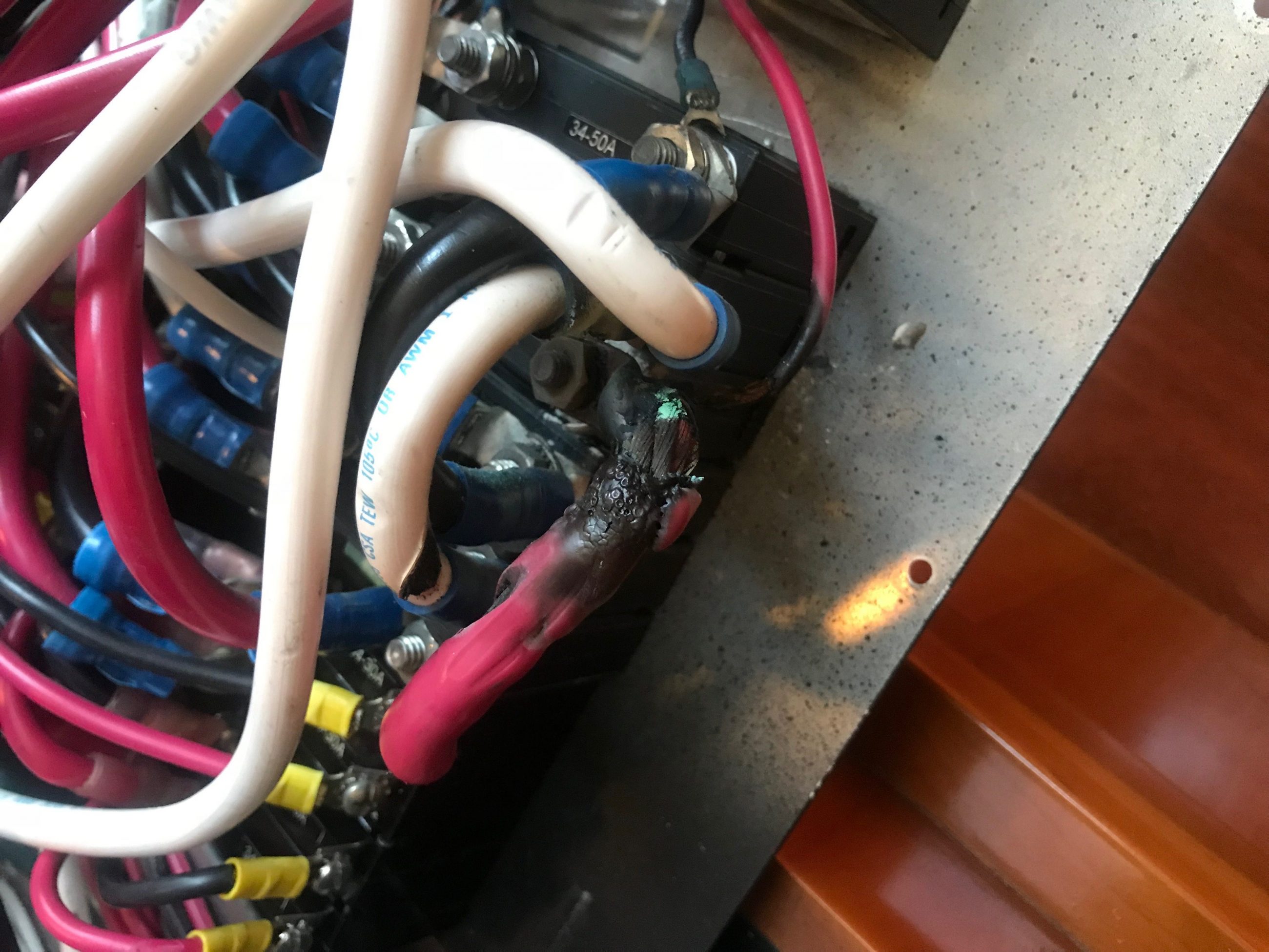
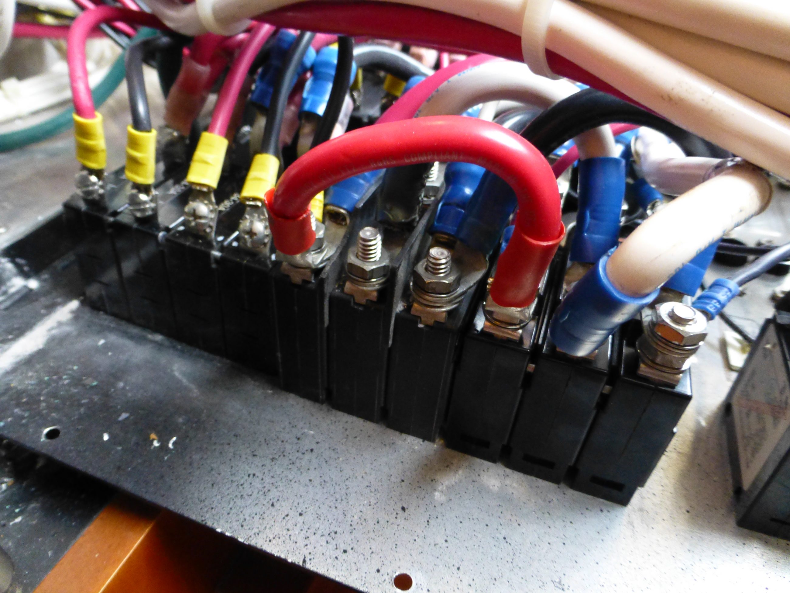
The sad looking picture above is the back of Have Another Day’s 240v AC panel. Though it doesn’t look good here, it was scarier looking when I first opened the panel the dull grey stud with the red 6 gauge wire was glowing red along with some of the wires exposed copper conductor. As soon as I saw the state of affairs I disconnected shore power and began investigating. The culprit was pretty easy to identify and turns out to be a matter of basic good practices not being followed when this panel was constructed, but realizing we had a problem was a matter of relatively subtle hints.
My family and I set out for a summer cruise from our home port in Chicago up Lake Michigan and over to Lake Huron to cruise the Georgian Bay and North Channel. We had a three day weather window in which the forecast on Lake Michigan consisted of nearly all zeros for wave height. That doesn’t happen too often and when it does it’s best to take advantage, so we plotted a course of three long days running in order to travel from Chicago to Manistique, MI at the top of the lake in Michigan’s Upper Peninsula. Our first day took us to Port Washington, WI.
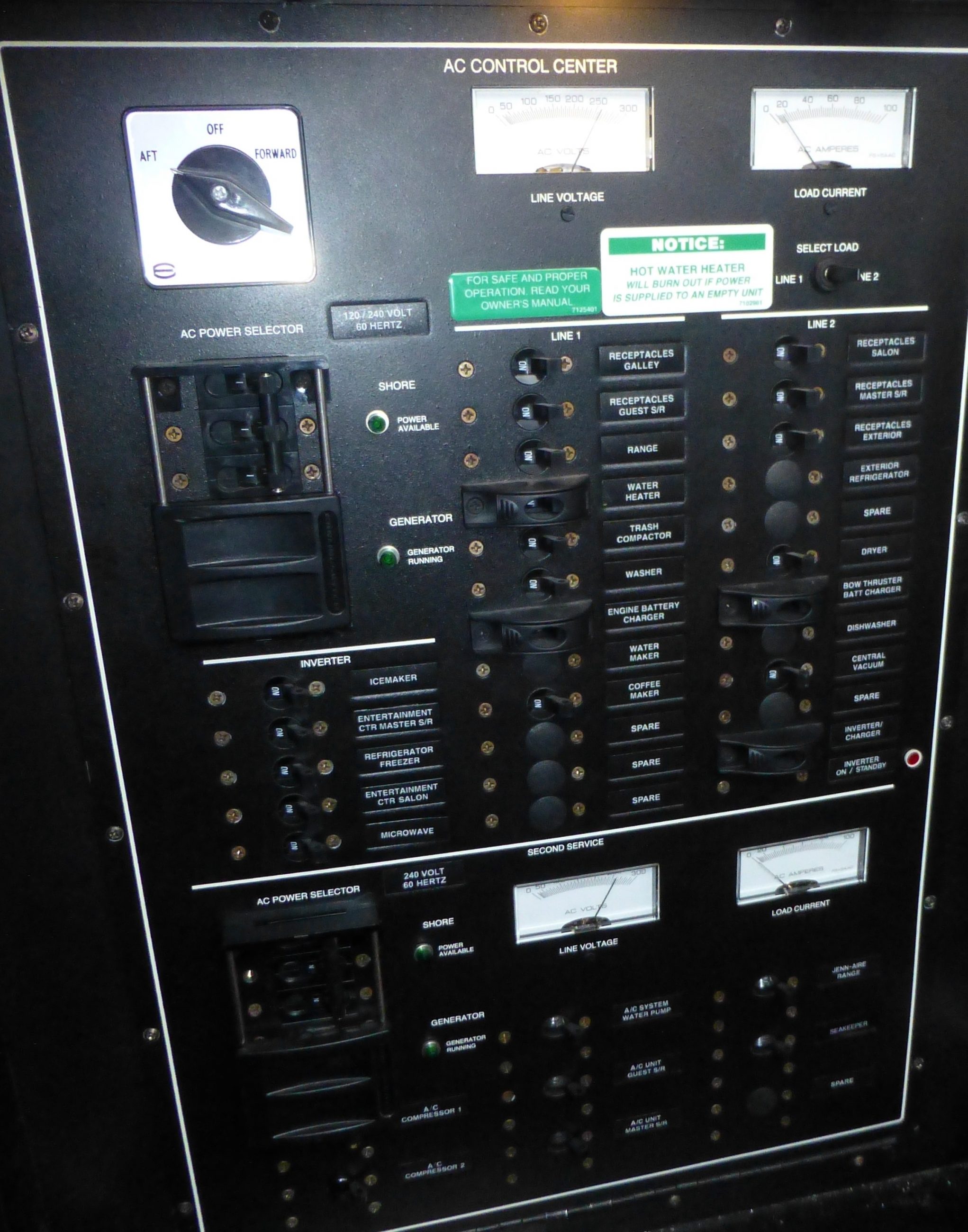
We arrived in Port Washington around 6:30 in the evening having been on the water for a little over 11 hours. Not exactly up to Ben Ellison’s 24 hour marathon, but a long day nonetheless, especially with two antsy kids. Have Another Day has two 50a 240v shore power circuits. As I glanced at the electrical panel just before transferring from generator to shore power I noticed that while on generator power we were only seeing about 200v on the 2nd (primarily air conditioning) circuit. With that piece of data I made a mental note to myself that I’d need to figure out at some point. Once load was transferred from generator to shore power the incoming voltage was now showing 190v and I knew my time to investigate was now.
Earlier in the season at Burnham Harbor we’d seen low voltage coming into the AC circuit, but that was on a 95+ degree day and I’d attributed that to voltage dip due to load at the marina. My boat is setup with isolating transformers on both shore power circuits but only shore power circuit 1 (which primarily feeds 120v domestic loads) has a boosting function in the transformer. This means that I can’t do an apples to apples comparison of the two voltage readings to identify a problem within the boat versus at the pedestal.
Now armed with the new information about low voltage readings on generator and on multiple shore power connections it was time to dig deeper. My investigation started, and as it turned out, ended at the main 240v AC panel. Upon dropping the panel I found the melted wire and cooked breaker.
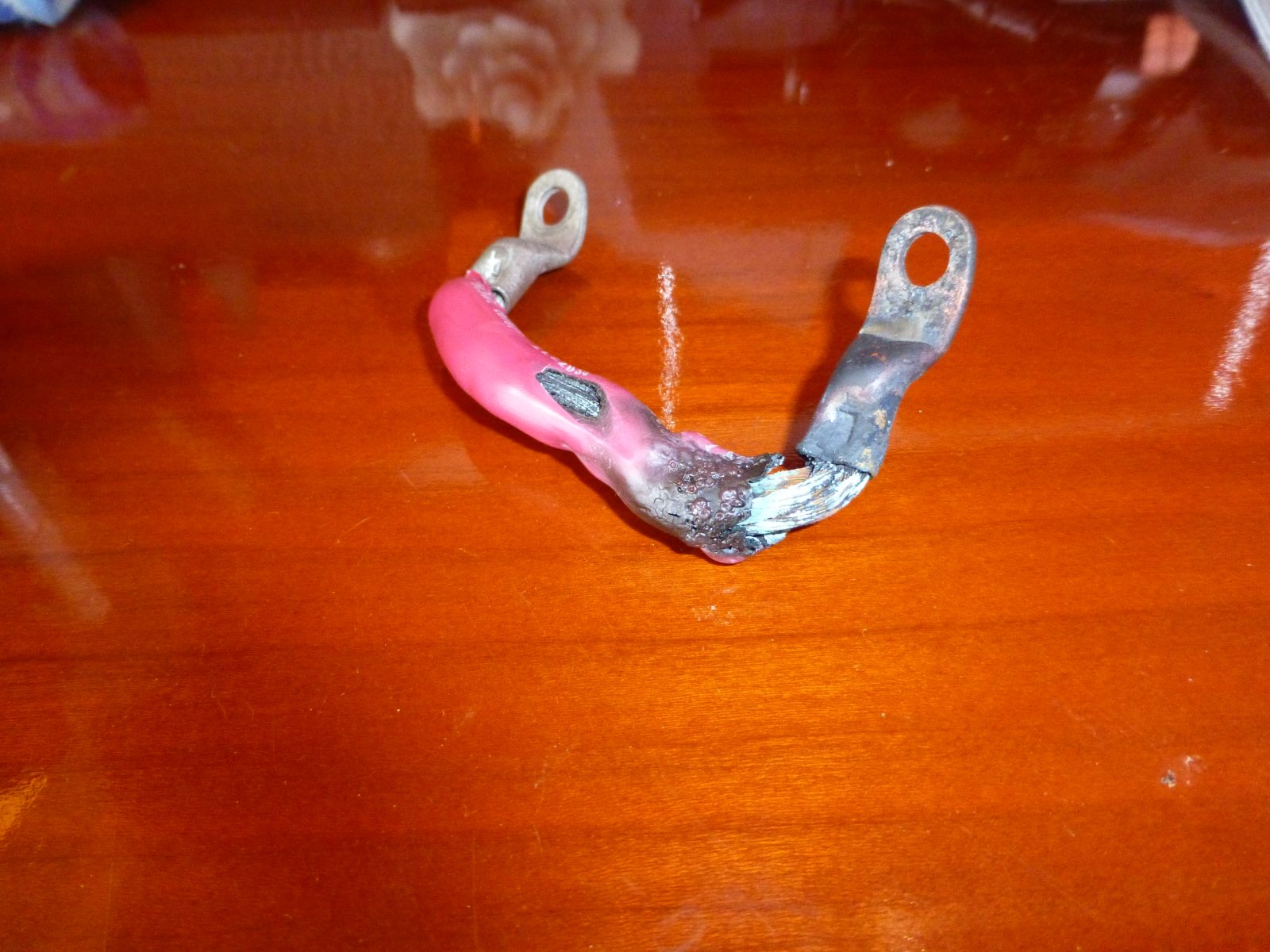
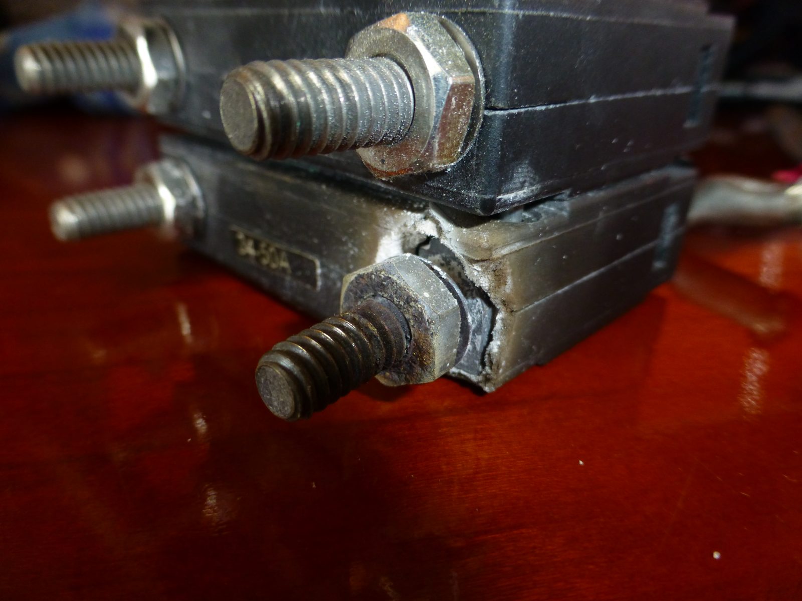
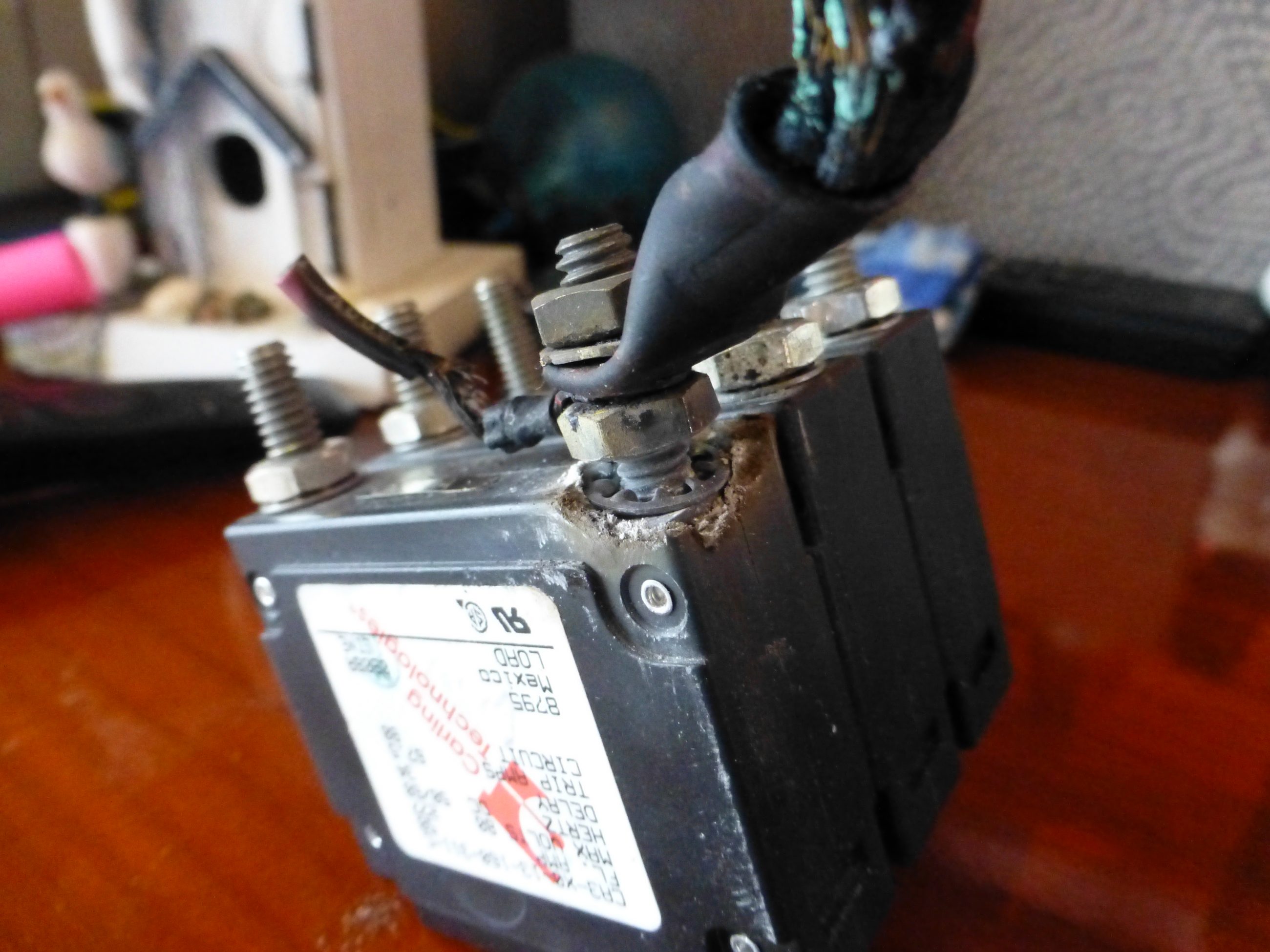 I didn’t get a good picture of the problem when the breaker was still in place but here’s my recreation of the problem. Carver employs a matched pair of breakers for each circuit with one for the generator and one for shore power. There’s a sliding lockout that prevents both breakers from being energized at once. The fried breaker above is the shore power breaker for the second circuit. The wiring in this area appears to be original to when the boat was constructed 15 years ago. What’s not easy to see in any of the photographs is the smaller gauge ring terminal (12 I believe) below the 6 gauge ring terminal. Everything I know about wiring says this is a no-no.
The largest conductor should be on the bottom with successively smaller terminals stacked on top, wedding cake style. That wasn’t done here, the smaller ring terminal that feeds the volt-meter was stacked under the larger one. Over the years and trips inside this panel the nut worked it’s way slightly loose, and it was truly very slightly loose. This created resistance in the connection, which, in turn, created heat. The heat melted the insulation, the breaker case and scorched the conductors.
I feel fortunate nothing worse happened. The insulation melted off this wire exposed a hot leg in close proximity to ground, neutral and the other hot . The enclosure for this panel has always seemed a little under sized. When the panel is pushed into place its front bows out from the pressure of the wires in the box and the lack of adequate space for the wires. I think this slightly too small enclosure probably contributed to the connection working its way loose. Carver is a price point builder and the electrical does reflect it some. There’s none of the lovely, groomed connections with terminal strips for each circuit. Instead, most of the wires are direct run to the load side of the breakers. The crimps are carefully done and the work has survived 15+ years of service.
 Upon figuring out what had happened I temporarily removed the melted breaker and jumper wire. I connected the line side supply to the distribution, which meant I didn’t have a breaker in the panel to interrupt load in the event of a problem. There is another 50 amp breaker for shore power where the shore power enters the boat, as well as the 50a breaker on the pedestal.
In removing the breaker, I’d also defeated the safety of the lockout preventing the generator and shore power from being energized simultaneously. Fortunately Have Another Day is equipped with both fore and aft shore power connections. To switch between the inputs there’s a rotary switch at the top of the panel. with aft-off-fore positions I was able to use that switch to turn off shore power altogether when using the generator and in so doing ensure shore power and generator power never meet. I was also very careful to only ever have one source of power available. So, if the generator was running the shore power cables were already disconnected and vice-versa for shore power.
Ward’s Electric in Fort Lauderdale had the breaker I needed in stock and had it to me in two days. Repairs were pretty simple to make; requiring a new breaker and crimping a new jumper cable. The greatest time was spent adjusting the way all ring terminals sat in order to make sure they were properly stacked and unlikely to become bent or pushed into contact with another conductor.
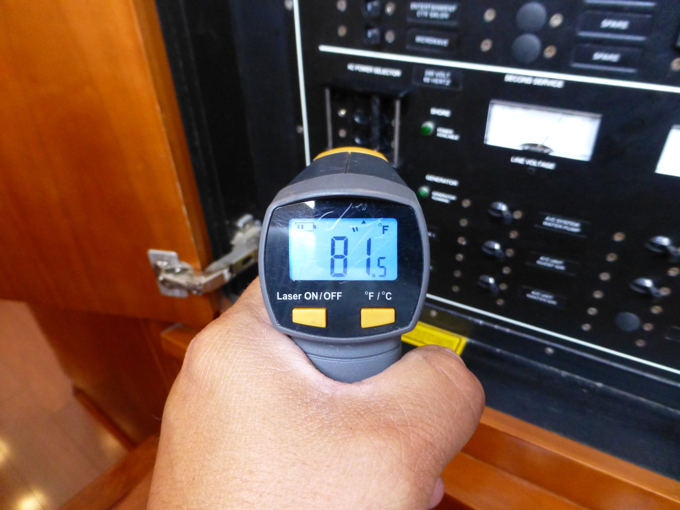
Lastly, I feel this is a good reminder to me and possibly others about the value of paying attention to the information available to you. Had I been more vigilant in noticing the declining voltage I likely could have found this problem before the electrical panel stood on the precipice of disaster. If I had scanned the AC panel with an IR thermometer periodically I could have found the increasing temperature of the face of the breaker. I’ll add the AC and DC panels to the list of things I try to periodically scan with an IR thermometer. When things break I’m frequently reminded how much easier it would be to diagnose and fix if I knew what the status should be when working properly.


Glad you found the panel issue and shared. This should be a reminder to all of us to be more diligent. I walk past my panel twice each time I go to engine room with IR thermo to do engine checks, and never thought of checking electrical panel. Thanks for the reminder great blog.
Could have very easily been a lot worse!
This is the stuff of old boat nightmares, glad you caught it!
It sure is. It’s the second time this season I’ve found very similar circumstances. The first time was on a friend’s boat, built in 1988. Obviously age plays a factor but vigilance regardless of age is wise.
I routinely advise my clients to install smoke detectors INSIDE every compartment that contains electrical breakers or devices. Hearing an alarm from these devices early, can help avoid a full blown fire. One more thought. Consider carrying one or two Halotron fire extinguishers onboard for electrical/electronic fires. The agent in a standard ABC extinguisher is highly corrosive, and can create a real mess, if discharged inside an electrical cabinet.
Glad it wasn’t more serious! It does seem that things are a bit squished and undersized, but that is not unusual in production boats from what I have seen.
Things are definitely much more squished than I’d like, but I haven’t found things to be undersized. In fact I have to give Carver credit for being fairly conservative in the design and build of the electrical system and choosing to oversize quite a few things. Including their decision to bring 100 amps of 240v shore power onboard. It could have been done on a very fully loaded 50a circuit but instead Carver used two. It’s sometimes a pain when travelling but it also means when we’re able to get the appropriate power we don’t have to stress any parts of the system.
But for some good luck where I happened to find some loose and corroded terminal connections in my yacht’s electrical distribution bus work, I would have experienced similar high resistance (temperature) electrical connector failure leading to an electrical breakdown and fire.
My personal opinion is that the stacking order of ring lugs cited as the cause is not the actual cause. It isn’t clear from the photos whether the electrical connector failure initiated in the staked connection from ring lug terminal to the jumper conductor or from mechanical looseness at the breaker stud jamb nuts. The simplest and more likely explanation is that the staked ring lug terminal connection to jumper failed, which created a hot joint, which due to thermal cycling caused the jamb nuts to loosen, thereby creating a second problem exacerbating the electrical joint temperature under load.
To prevent these types of failure modes on my boat I do the following:
1) I fabricate jumpers from copper flat bar and tin the copper bus rather than use a loop of single core cable.
2) Every electrical cable on the boat is marine grade (tinned copper strands) single core cable.
3) Every electrical cable termination is crimped (using Amp PIDG style ratcheting crimpers and tinned ring lugs) then solder sealed. We do not allow “staked” style electrical terminations.
4) we brush Dow Corning #4 dielectric silicone grease on the terminal stud/bolt and ring lug before tightening the mechanical fasteners.
5) for electrical terminations that are subject to vibration, we secure the conductors with lacing tape and/or one-hole cable clamps to shunt mechanical cable forces from the electrical joint’s fasteners.
6) we apply a removable thread locker to the fastener threads before securing the mechanical connection.
7) in cases where the air gap space between phase/bus poles are small, we install dielectric barriers between phases or bus poles, and or we apply an electrical grade anti-tracking varnish (Glyptal) to the termination. Glyptal acts as a thread locker also.
No boat builder I am aware of follows the proscription above, but this is for commercial reasons only. Nevertheless this is method to achieve a reliable and safe electrical system aboard a yacht.
Electrical panel breaker/switch terminal joint tightness should be verified annually.
Another failure mode exists at the shore power cable’s receptical in the boat cabin trunk, the run of bus cable from this receptical to the AC panel can also initiate an electrical fire from failed terminations.
The shore power cable probably doesn’t use tinned copper stranded conductors, so the cable can initiate an electrical fire.
IR scans are well proven maintenance technology, but you have to “shoot” the terminals when they are operating at rated load. Scanning the panel front may result in missing some compromised electrical joints.
BR
Marcus
Marcus,
I too feel quite fortunate not to have had a fire given the state of affairs. Thanks for the thorough list of steps you follow. I’d love to adopt some of the processes you follow but will also admit this would put the modified connections way ahead of the large number of existing runs. I’m not in a position to be able to redo the entire boat.
I agree about shooting the front of the breakers not being the ideal point at which to measure. I’m curious if you have any thoughts about ways to shoot the terminals. My panel is hinged from the bottom, secured by about 12 screws and difficult to get back into position. I’m confident the benefit of being able to measure temps on the backside wouldn’t be worth the increased risk of opening and closing the panel on a highly regular basis. In this case I feel getting the front measurement is better than nothing.
Ben
Hi Ben,
Bottom line is you’ve done everyone a service here by pointing out this issue.
Boats need to be built to be serviceable and frequent inspections are part of that. Properly torqued, those nuts shouldn’t come loose no matter how much you opened the panel.
One thing I can’t stand is an overstuffed electrical cabinet. I’ve not worked on the bigger Carvers (yet) but I’ve worked on a number of other makes. Some of the worst designs I’ve seen are in boats like Hatteras and Grand Banks, and some of the best I’ve seen include ‘price point’ boats like Mainship as well as premium makes like Beneteau.
I get the sense that many boat manufacturers (regardless of price) seem to view the electrical system as an afterthought, and most pay thier electrician the same rate as they pay for grunt labor. Pretty sad considering that the majority of boat insurance claims are due to electrical issues.
Anyway — glad you cought this AND took the time to share. Thanks!
Stacking smaller terminals beneath larger terminals creates a condition where currents greater than the smaller (lower) terminals are rated to carry. This necessarily creates heat. It’s the most common cause of voltage drop problems when untrained people work on batteries where the usual symptom is reduced engine cranking power. Since that is momentary it gets overlooked most of the time. However, a continuous load as would be seen in a power panel is a recipe for big trouble from sustained overheating. All the extra steps mentioned are lauded but do not prevent overheating caused by poor installation practices. ABYC calls out the proper practice for a good reason.
The ABYC spec refers to a terminal’s “base”:
“11.14.4.1.10.1 Multiple conductors connected to a terminal stud shall be installed with the highest ampacity conductor terminal closest to the base, followed by successively smaller ampacity conductor terminals.”
The “base” of a battery terminal or bus-bar presents a large, conductive surface area and the largest lug should indeed be placed on the ‘base’. Moreover, threaded battery terminals and copper buss bars present significant thermal mass. As such they are able to function as both a heat sink and as a means of dissipating heat.
Look carefully at the photograph. You will see that there is no ‘base’ on this stud. Both terminals are clamped between two identical nuts. Because this terminal has no ‘base’, the surface area of contact clamping is identical no matter which way you stack those two ring terminals, and the ability to dissipate heat into the stud is (if anything) better for the large ring terminal BECAUSE it was placed at the top.
Most marine electricians won’t think this hard, and they shouldn’t have to. The ABYC guidance is simple and should be followed regardless. However, make no mistake. This termination overheated and the stud and wire were fried because the nuts were loose. In this case, stacking order had nothing whatsoever to do with it.
Hello Ben:
First, thank you for your ongoing efforts to manage this valuable resource for the yachting community.
Implementing the wiring techniques I recommended will result in rewiring the yacht; speaking from experience after spending many evenings and weekends to rewire the main circuits on my sailboat (complete is the wrong term, I got most of the circuits replaced but not all). I justified the rewiring project on the fact that the boat had completed an 8 year long circumnavigation of the globe, which resulted in many “hands” working on boat’s electrical systems during this period, which resulted in a convoluted mess of an electrical system when I “blissfully” acquired the sailboat.
The electrical panel on my boat is piano hinged at the bottom edge, and it has an acrylic plastic door to cover breaker toggles to prevent accidental switching. I use two screws to at the top right and left frame to secure the panel in its frame. These screws are well worn due to frequent removal and installation.
IR measurement of the termination temperature requires a direct line of sight to the subject studs/poles. The only practical way to accomplish this is to swing the panel down when circuits are under load.
Alternatively, a “keep it simple” approach (that also requires swinging the electrical panel to the maintenance position) is to wiggle each connection by hand…if there is movement of the connection lug on the stud, the connection clamping is too loose. Also any sign of corrosion on conductor strands, ring lug, terminal stud or jamb nuts indicates a problem is developing. Any sign of oxidation to breaker housing “bakelite” also indicates a problem is developing.
Luckily these types of connection failure modes develop slowly, which gives us time to make intervention before final failure occurs.
I tend to agree that the stacking order of the ring terminals was not the primary root cause here. It may have contributed slightly, but the real problem is that the nuts were not torqued properly in the first place. The stud itself IS the conductor and if the nuts on either side of the stack were tight, both ring terminals would conduct into the stud without overheating.
I just saw a similar near-disaster on a nineteen-year old boat that was caused by loose stud nuts at a panel ammeter.
More importantly, the REASON they became loose is because the manufacturer used overly stiff (non-UL 1426) wiring attached to a Modutec 50A AC Panel ammeter. Routine maintenence of the panel and the stiffness of the wiring invariably caused the connection to loosen further. There were no other ring terminals on this stud — so this near disaster was purely the result of loose stud nuts.
Contrary to many popular misconceptions, the most important reason to use UL 1426 ‘Boat Cable’ is not because it is tinned. In fact, UL 1426 does not even specify that the wiring be tinned. The most important feature of UL 1426 wiring is that is has a very high strand count, therefore it is very flexible and will not put stress on terminations when moved about or when subjected to vibration.
As soon as time permits, I will be posting a detailed failure analysis — hopefully including comments from Modutec around proper termination and wiring of their devices.
Lastly, in a small defense or Carver and other ‘price-point’ builders, there is nothing wrong with their DESIGN that I can see. All of the wiring appears to have been well chosen (appears to be UL-1426) and the Carling breakers are as good as you can get. The problem here started with the ham-handed assembler who failed to torque the nuts properly. If Carver is to blame here, it is for their lack of training of their assemblers, not the designers.
Eric,
Thanks for your comments and point well taken about the size of the contribution the stacking order represents.
I think if anyone is to blame for the nut working itself loose on the stud the best candidate is likely me. I’ve opened and closed that panel quite a few times and I suspect that, due to the size of the enclosure, I’ve had to move the conductors and that may well have contributed to the nut backing off. I do feel Carver has a bit of a design weakness in the size of the electrical enclosure. Were it a bit more generously sized it wouldn’t be necessary to cram the wires in (and likely move the ring terminals in the process).
I might also take a second to clarify my price-point comment. I didn’t mean anything negative about Carver, who I think overall has built a boat to a market segment very well. What I did mean to imply is this boat isn’t built with the budget of a Grand Banks, Sabre, Fleming, etc. and as such there are cost considerations that must be made. I think Carver has done an excellent job (mostly) making trade-offs that contain cost while not sacrificing safety or violate basic standards.
Since I originally responded, I have seen yet another near disaster — exactly the same failure mode.
Once again, it was in the circuit that feeds the air conditioners. High (summer) temperatures outside, all Air Conditioners running at max load inside the boat, loose connections at the stud terminals. Both the stud and the lug get red-hot.
Everyone reading this article should check the terminations for both the hot and neutral wires that feed your highest electrical loads on the boat. Don’t rely on on just an IR temperature check! Examine all the terminations carefully, look for any signs of past overheating. Check the torque on the stud nuts. Try to determine if UL 1426 wiring was used and if it is tinned. Pay careful attention to the terminations on rotary source selector switches, non-transformer type ammeters and (of course) breakers and bus bars. Examine your boat’s shore-power inlet (male) connectors from outside the boat — any signs of overheating seen near the male connectors probably indicate a loose termination where the wiring is attached to the inside of the inlet connector.
This summer alone I have replaced three shore-power inlets (and three consequently damaged shore power cables), one 50A breaker and one 50A panel ammeter — along with melted wiring.
All of these were due to loose or poorly terminated wiring — all manufacturing defects, and all of these were very scary for the owner(s).