
DIY LiFePO4, the build begins
In the last couple of months I’ve installed two of the three main types of lithium iron phosphate (LiFePO4) batteries. In March I installed Mastervolt’s system integrated MLi batteries on Have Another Day and just last week I finished up the installation of Battle Born’s 8D drop-in batteries on another boat. With two out of three types covered I figured it was time to get my hands dirty with the third type, a do-it-yourself build of a 12-volt LiFePO4 battery.
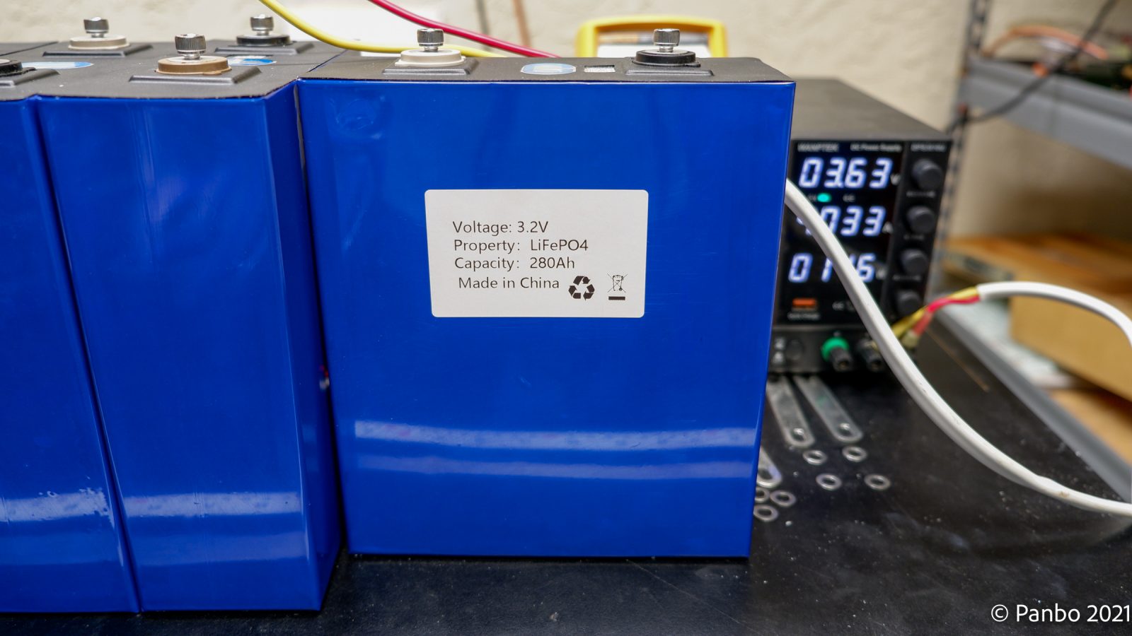
The data plate on one of the cells I’m using 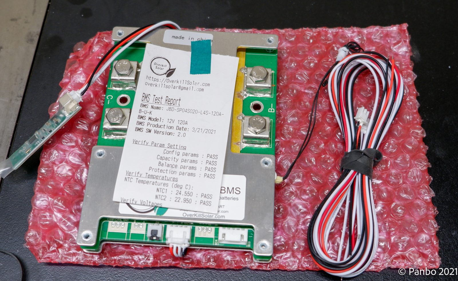
Overkill Solar’s 120-amp BMS


For my DIY LiFePO4 battery, I picked four, 3.2-volt, 280-amp hour cells direct from China via Aliexpress. The batteries took about two months to arrive, which isn’t surprising for heavy items with the current international shipping challenges. The seller says these are brand new cells and they look it, though I’m not sure I’d know if they weren’t. I selected an Overkill Solar 4S, 12-volt, 120-amp BMS paired with my batteries. Although the BMS was back-ordered, it arrived a few weeks later and well ahead of the batteries.
The batteries’ specs aren’t overly clear but they appear to be able to sustain 1C continual load or 280 amps. I don’t have a specific application for this battery yet and felt that 120 amps was likely to be enough for any use I dream up for the batteries, so I stuck with the 120-amp BMS.
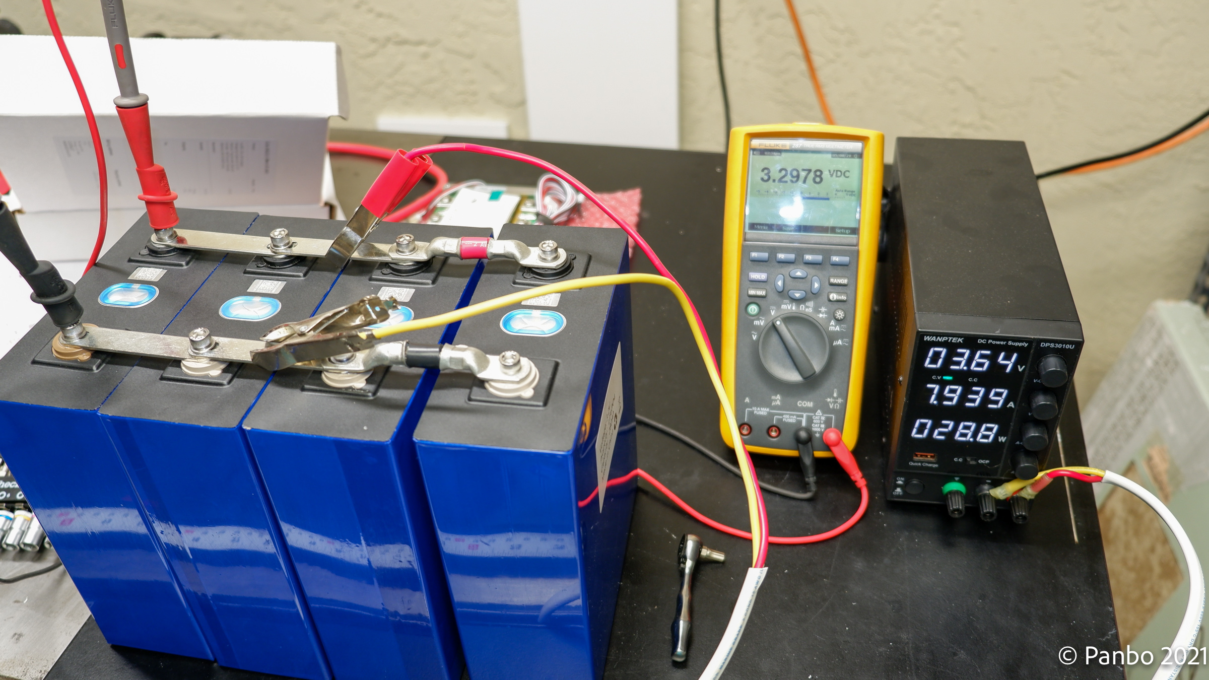
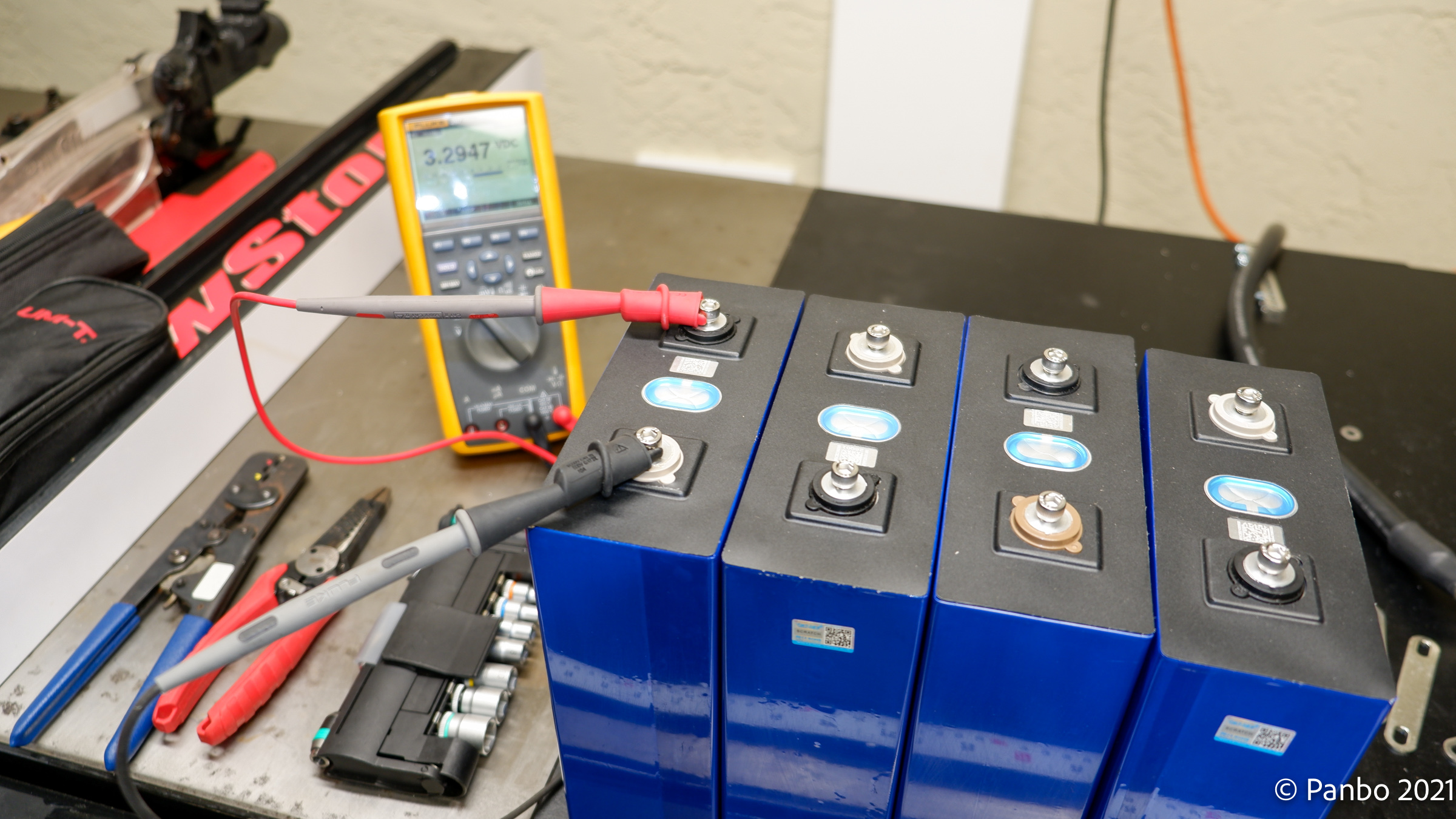
The first step of my build is to get all four batteries balanced at the same voltage. In the picture above all four batteries are connected in parallel and a 3.65-volt charge is being applied. As you can see on the multi-meter, the batteries are about 0.3 volts below that charge so it will take a while for them to reach top balance with all four fully charged and balanced with each other. Once that’s done it will be time to move on to connecting the BMS and physically connecting the four cells into a single battery.
I’m a rookie, so I’m taking it slow and being as careful as I can. If any of you who have done this before have words of wisdom to share, I’m all ears. Otherwise, I’ll just be here waiting for my meter to edge up to 3.65 volts.


Top balancing takes a long time. I have a 10-amp bench power supply and I’m trying to top balance 1,120 amps of 3.2-volt cells. In about four hours I’ve brought them up .0012 volts, they need to come up about .35 volts.
-Ben S.
2,5 A per battery, sure, that is going to take a long time. Lithium cells have a pronounced hockey-stick charge – voltage diagram, so you will find that they remain stable in voltage until they are _almost_ full then the voltage starts rising quickly.
> I’m trying to top balance 1,120 amps of 3.2-volt cells
Ben, please don’t be casual with units when batteries and electricity are involved. It is hard enough for readers to keep their heads around this without you writing “amps” when you mean “amp-hours”. You meant to write “1,120 Ah of 3.2 V cells”. “Yes but it is hard” is IMO no excuse when you are a journalist writing about this.
Kees,
Mea culpa, I did indeed mislabel the unit of capacity on the batteries. Wired in parallel, the four 3.2-volt, 280 amp-hour cells yield a total capacity of 1,120 amp-hours.
Also, indeed as you mention, given the very stable voltage of LiFePO4 chemistry batteries I don’t expect much fluctuation in voltage until the cells get very close to 100 % state of charge. I’m at about 18 hours of charging right now, which means I’ve probably replaced about 180 amp-hours of energy, perhaps another day or two to go.
-Ben S.
But as a 12 volt system it will be 280 aH.
Joel
Yes, you’re correct. The 1,120 Ah figure is only relevant while top-balancing the cells in parallel. So, once this step is done I can charge at 12v nominal (higher actual voltage from the charger) which will cut charge times by four.
-Ben S.
Ben, I was thinking of buying a kit similar to yours here: http://lithiumbatterykit.com/.
Is there any way to judge the quality of the cells?
I don’t know of a way to assess the quality of the cells. I think you could contact the seller and ask if they have any reports on the cells. But, overall, you’re likely placing your trust in the reputation of the seller. In this case, I know nothing about the seller, so you may have a leap of faith involved.
You’re definitely paying for the top balancing, US warehousing, and kitting the seller has done. My total cost for the 280 Ah batteries and BMS was around $600. There are additional components included from this seller that might add another $100 or so. But, I also have all the tools, wire, and connectors needed on hand which makes the build easier for me.
The one question I’m left with is how the seller can ship these batteries top balanced. My procedure for top balancing will have me connecting to the BMS fully charged. My understanding of U.S. shipping regulations limit batteries to 30% SOC for shipping.
-Ben S.
I wouldn’t purchase cells that were top balanced by the supplier. LiFePo4 should not sit fully charged. If the supplier top balances how long do they sit on a shelf fully charged – months?
As far as supplier I purchased Calb cells from one of the main distributors in China. Much less expensive that buying from elsewhere.
I had in mind to do exactly what you are doing but I’m stuck on something. How do I charge these with an alternator? When they are fully charged, the BMS will disconnect them and the resulting spike will damage the alternator. Sterling makes an alternator protection device. That might work. I’d prefer a BMS that could signal an impending disconnect…
Andreas,
First, at least with regards to the BMS I’m using (from Overkill Solar), the BMS doesn’t disconnect when the battery reaches full charge. The cells taper to accepting nearly zero amperage, but there’s not a disconnect event. The only time there’s a disconnect event is when a cell or the battery as a whole violates the over-voltage thresholds. In my normal charging thus far, with the bench power supply set to 14.4v I haven’t seen this event. I did force it by setting the power supply to 14.8v with a fully charged battery. That quickly resulted in the BMS shutting down charging — as it should.
I think (but I’m still learning here as well so everyone should feel free to chime in) you have several options to avoid damaging your alternator. First, and possibly the safest option because it changes the charging system as little as possible, would be to maintain a lead-acid battery for engine start and then use a DC to DC converter from the lead-acid battery to the LiFePO4. That way your alternator is only connected to a battery that’s not ever going to disconnect. The second option is indeed an alternator saver like you mentioned. I don’t believe the Overkill BMS has an external trigger to shut down the alternator, though it would be nice.
-Ben S.
I tried this setup with the alternator charging the start battery and a DC-DC converter charging the LiFePO4 batteries. I used two Victron Orion TR 30 amp DC to DC converters. The problem was that the converters get REALLY HOT and drop their output to less than 20 amps each.
I’ve since changed the system so that I’m charging the LiFePO4 bank from the alternator (with a Balmar regulator) and am using a Sterling alternator protection device. I am now using one DC-DC converter to change the start battery. This is working out very well and performed flawlessly on a recent five week cruise.
My before and after system diagrams can be found here: https://twoatsea.com/auckland-boat-projects-3/
This makes a lot of sense when considering the flow of energy through the boat. I’ve been hesitant to go the route you describe only because I like the idea of disturbing the engine 12v system as little as possible. I’m using a Victron Orion TR on my RV to charge from engine start to house (though currently, they are both lead-acid). I haven’t noticed the converter getting hot but it lives in a pretty well-ventialted area that’s seeing a lot of airflow when the RV is moving along at 60 mph.
-Ben S.
Rich, question for you. How big is your Balmar alternator and what AMPs do you see coming out of it?
I just had a chance to use my brand new DIY 200ah Lifepo4 bank for over a week. As far as charging it I only see 20amps at the start of the engine which drops to sustained 15A. This is going into the battery. I dont know how much is coming from the alternator. I havent had a chance to see if the internally regulated 60amp alternator heats up or the DC-DC Orion drops it because it gets too hot.
My alternator is 100 amps but I’ve never seen that much. When it’s cold, I can get almost 90 amps for a short time (maybe a minute or two). Then it drops so that I get about 65 or 70 amps from it.
I have also had to de-rate the alternator using the “belt manager” setting in my Balmar regulator. I have it set to B1. Without this setting, the alternator gets too hot. (I have a temperature sensor on the alternator so the regulator will cut the power if the alternator gets too hot, but the temp climbs fast then the power remains at about 50% for a long time. With the belt manager set to B1, I get longer charging periods at 60 or so amps without overheating the alternator.)
My Balmar regulator (MC-614) must be an older version and doesn’t have a lithium battery setting. I’m using the “halogen” setting with some adjustments and that’s working well.
I was hoping to build four 280AHr battery packs, and wire them in parallel.. that would give me 1120 Ahrs. That’s 13.44kWh 🙂 I could even run a small A/C unit off my inverter for a few hours 🙂
To recharge that battery bank, I actually considered not using the alternator at all, and just going with shore power/genset and solar charging only. Not as nice as having the alternator charge while we cruise, but very usable. I’ll figure it all out eventually.. I’m also still learning about having several LIFEPO4 batteries in parallel.. each one has 4 cells and a BMS.. what happens when one of the prallel packs experiences a problem and disconnects? I almost need a BMS to keep track of the battery pack.
Maybe I’m overthinking this.. So much to learn 🙂
Andreas,
Good question you brought up in your first post. This great article talks about two different alternator damage situations and ways to protect them.
https://livsailing.com/2019/11/04/protecting-your-alternator-when-switching-to-lithium/
Still, personally, I would resort to only DC to DC charger simply because I can never be comfortable pushing 80, 120, etc. amps that big alternators put out through the wires on my sailboat.
My needs are pretty conservative. Even with all possible systems turned on i only use 5-6amp hour. My battery is 200ah.
With the big battery bank like yours my solution may not work for you.
Will Prowse tested these batteries and was impressed.
https://www.youtube.com/watch?v=3U4ZfQ_IToI
how can one take advantage of fast LFP charging to minimize engine run time if they are charging into a LA battery and trying to charge the LFE with a DC-to-DC converter only capable of 50A or so?
I want a minimum of 250A of steady charging current into my LFP bank from my twin 150A alternators.
Really don’t understand this.
Mastervolt and Victron allow the connection of DC-DC chargers in parallel 5x50A = 250A
Thanks Christopher, but 5 converters in parallel? Ouch?
I am installing the 800Ah Blue Lithium bank to directly be charged by the twin 150A alternators (thru a battery selector switch). The other side of the switch will optionally connect to a 100Ah AGM reserve battery that will be kept charged on a DC to DC converter off the lithium bank. See any issues?
Yes there is an issue. You need a controller on the output of your alternator to prevent it from burning up and actually catch on fire. Your LithiumS are no doubt rated at one C which means they could very well call for 810 amps if you let your Lithiums go all the way down to 10% SOC. This will burn up your 80 amp alternator.
Bill,
I would like to make a point tangential to your concern.
It is a common misconception that lithium batteries have a higher practical charge acceptance rate than quality AGM batteries such as TPPL AGMs which we have standardized on.
There are no limitations on charge current on these AGM batteries, whereas marine lithium batteries, by comparison, are severely restricted by the mfgs in regard to recommended charge rates.
Just look at the specs on the Lithium Blues above. Or even the more robust and heavy duty well tested MasterVolt line.
People often confuse the longer time it takes to get the last 10-15% into an AGM battery, with it having an inferior Bulk charge acceptance rate.
I can assure you that our present 860Ah AGM bank, with no limitations on how big a charging source it can be connected to, has the ability to take 300A in Bulk charging mode. And in a much safer manner than lithium. You don’t have to safe guard these AGMs from very large charging sources as you do with lithiums.
I find it ironic that you can hook up a 300A alternator source to a 50A AGM without issue, but you would typically need 6 lithiums rated at 100Ah each to stay within the mfg’s recommended charging specs.
Having said that we have temperature sensors on our alternator sources that keeps them protected, yet reduces there full charging performance very little.
They have been in service for 10 years now and are still going strong. They won’t care WHAT is putting a load on them, only what their internal temperature is.
I find it ironic that you can hook up a 300A alternator source to a 50A AGM without issue, but you would need typically need 6 lithiums rated at 100Ah each to stay within the mfg’s recommended charging specs.
Where quality lithium batteries shine is there high current output at low states of charge, hence our interest in them – if they actually live up to that performance promise.
Weight savings will be appreciated too.
Best,
Lawrence
Lawrence,
I have to respond to several of the assertions you’ve made. I don’t think what you’ve described tells the whole story.
First, you note that there are no limits on charge current for AGM batteries. That’s not what my experience has shown and it’s not what I’ve seen recommended by battery manufacturers. For example Rolls (http://support.rollsbattery.com/en/support/solutions/articles/4345-agm-charging) states:
We recommend a charge current of 20% of the 20 hr rate for both Bulk & Absorption charge phases on AGM & GEL VRLA models.
[10% min, 20% recommended, 30% max]
That 30% maximum is 0.3C. Quality LiFePO4 batteries are typically rated for 1.0C or 100% of rated Ah capacity. Inexpensive batteries might be at 0.5C but 0.3C for a LiFePO4 battery would be lower than nearly any specs I’ve seen.
Additionally, I think you’ve blurred the length of Bulk and Absorption cycles when you describe the time it takes to get the last 10-15% of charge. That additional time is because of the lower charge acceptance as the battery approaches 100% SOC. And, it’s a double-edged sword for AGMs, SLA, and FLA batteries because without achieving 100% SOC you’re also not clearing sulfation from the plates and risking lasting damage to the batteries.
Lastly, I think you’re comparing different charge acceptance behavior and deciding it’s indicative of the superiority of one chemistry over another. It’s true that lead chemistries typically protect the alternator because of their higher internal resistance and lower charge acceptance. It’s a happy circumstance of their charge characteristics, but it’s also part of why they take longer to charge. LiFePO4 and other lithium chemistries don’t have these limits on charge acceptance and as a result, the alternator needs to be protected from killing itself delivering all the power the battery will accept. I think that situation will improve over time. The vast majority of alternators in the world were designed and built long before batteries with differing charge-acceptance behavior existed. So, we will need to adapt.
-Ben S.
Ben,
From the MasterVolt 12/5500 400Ah battery manual:
“Recommended charge current ≤ 120 A”
That’s 0.3C, no? And this is a high quality lithium battery. And the most expensive I have seen.
I have never seen a lithium battery with a recommended charging current of 1.0C
Do you have an example?
From my Enersys AGM manual:
“there is no need to limit the inrush current, allowing the battery to be rapidly charged.”
And I note there is no caveat whatsoever on charge current limits in their specs, as with the MasterVolt battery.
Also, I am referring to BULK charge acceptance rates when comparing lithium charging rates to our AGMs. The slow Absorption and Float times for the last 10-15% are not relevant when the goal is to alternator charge in the briefest amount of engine run time, such as one does at anchor to make the day’s amp hours for house loads.
In our case that is around 250Ah. This is easily achieved in one hour as you watch a sustained 250A for an hour go into the batteries, and then you shut down the engine.
In regards to holding sulfation at bay, 10 years ago the chief technical officer at Enersys told me that a full charge every 7-10 days takes care of that. And I can report it has. Its easy to do on windless passages when the engine runs 8 hours or more. All too common in cruising. In fact, happens several times a week. And of course any time with shore power in a marina does the same.
And I find this direct quote from the same MasterVolt 12/5500 400Ah battery manual interesting (page 21):
“To prevent damage the batteries must be charged to the full 100% regularly. It is a common misconception that Lithium-Ion batteries should not be fully charged.”
Not sure I agree with that as my Tesla manual differs, but it sure contradicts a big perceived advantage of Li over AGM if MasterVolt is right.
With regard to your last paragraph I am confused by your statement of lithium not having charge acceptance rates issues as with our AGMs.
From the recommended charge limits appearing in the manuals I have read, I can only conclude its the opposite.
I think one difference perhaps in our individual perspectives is that I am alternator charging centric, and with our SOP of Bulk charging only, the generalized issues you are referring to simply don’t manifest. I am not trying to make the case for AGM vs Lithium, just trying to stay objective about the application realities of the choice.
Cheers,
Lawrence
Lawrence,
Thanks for the interesting discussion. This is new technology and the dynamics have changed. Lead-acid batteries don’t have a BMS involved,which means the parameters are only about maximizing cell life. In LiFePO4 batteries it’s difficult to know if the limits and recommendations are made to preserve cell life, to protect the BMS, or both.
First, you’ve correctly pointed out that I didn’t pay enough attention to the recommended versus maximum charge current. For example, a Mastervolt MLi 12/5500 ultra battery does indeed list a 120 amp (0.3C) recommended charge current. But, its maximum charge current is 400 amps (1C). Compare to the Rolls battery specs at 0.2C recommended and 0.3C maximum.
But, it also seems like Mastervolt is more conservative in how they rate their batteries. Battleborn doesn’t list a recommended and maximum, instead, they just list a single number of 0.5C (https://1t1pye1e13di20waq11old70-wpengine.netdna-ssl.com/wp-content/uploads/2019/01/BB10012-Spec-Sheet.pdf – second page of the spec sheet in an FAQ), Lion Energy also only has one number, but it’s 100 amps for a 100 Ah battery or 1C (https://lionenergy.com/collections/batteries/products/lion-safari-ut-1300). Lithionics shows a recommended charge current of 50 amps on a 130 Ah battery (0.38C) (https://lithionicsbattery.com/product/12v-125ah-g31-battery/) and a maximum of 100 amps (0.77C).
Mastervolt’s charge recommendation is the lowest of any of the majors, but at 1C for maximum they’re in range with the others. I’m going to reach out and ask them the difference to the battery between recommended and maximum charge current. Does charging at maximum reduce cycle life? Produce more heat? Shorten BMS life? I’m curious to know the difference.
As for the 100% charge recommendation, first of all that was a good catch. It’s in a weird section of the manual focused on MasterBus events. I haven’t seen any other LiFePO4 manufacturer make that statement or recommendation. And, as you mention, it flies in the face of much of what we’ve heard about ideal use of these batteries. It’s often recommended that the absolute longest life comes from a maximum charge of about 80%.
Again, I thank you for the interesting discussion and challenging me when I’m wrong.
-Ben S.
The recommendation to charge periodically to 100% might be to allow the BMS to balance the individual battery cells. Balancing works best when the charge current is small, as it is when the battery is almost at 100%. Also, some BMS units don’t even start to balance until a threshold voltage is reached.
Richard,
Thanks for chiming in. Not sure why it didn’t click for me before. I’m sure you’re right that the 100% recommendation is about cell balancing.
-Ben S.
For a lithium battery pack, often the maximum charge current is set by the limitations of the BMS, not the cells themselves. For example, I have a 48V, 300AH pack powering an electric runabout. If you look a the battery cell specifications, the maximum charge current is 2C or 600 Amps, but the BMS specs say 200 Amps maximum. So while the cells can handle 600A, the pack as a whole is good for only 200A based on my choice of BMS. Had a spent a bit more, the maximum charge rate could have been higher.
Bottom Balance only on new installs.
I’m an electric vehicle tech/ emobility specialist.
Check my channel out, it might help on a future build.
https://youtube.com/channel/UCbOo4Qc1XOL2juUvUiOp28g
For a marine LiFePo4 pack – assuming cells with separate BMS – top balance, not bottom balance. Electric vehicles are very different in use than boats. On a boat it is rare to get near the bottom, unlike a vehicle. It is most important that the cells in a marine system are in balance at the top.
FWIW, I recently finished with the DIY LiFePO4 battery install on my 38′ MT AC trawler.
I did something similar, but went a bit larger. I got 310Ah cells from Alibaba and four 200A continuous Daly BMS. I wanted enough energy storage to run the aft cabin A/C for a night ( it doesn’t have to cool a lot, just take the edge off and pull some humidity ) and enough current capacity to start the main if needed, though I’ve got two group 27 AGM’s to do that task under normal conditions. It’s essentially doubling the usable capacity of the previous flooded cells in less space and weight than the old batteries.
Both the cells and the BMS arrived in good condition and the batteries appeared to me to be matched cells without blemishes.
Top balancing all of those cells with a 10A power supply can take a while, so I used the BMS to monitor individual cell voltages ( it’s got a BT module ) while I charged them in series using a 35A battery charger. This got most of the charging out of the way pretty quickly without going over the max cell voltage and let me top balance in only a day or so per battery.
The instructions that came with my cells said that their lifespans would be longer if they were installed with about 10 PSI compression to prevent swelling. I used plywood end plates and three large 250lb zip ties to bind them all together, tightening the zip ties with a big slip joint pliers until the ties were tight enough to thrum when plucked. The aluminum cases of each cell are not isolated ( I think they’re positive? ) and I wasn’t totally sure of the abrasion resistance of the thin plastic the cells are shrink wrapped in, so I added a layer of inexpensive thin cutting board plastic between each cell as I assembled them.
These battery modules were small enough to fit into a plastic group 27 battery box, so I used those as a case. I drilled holes in the lid for the sense wiring and the negative cable and attached the BMS to the lid with nylon hardware, so there were no conductive elements holding everything together.
All four batteries tested on my capacity tester at 95% of rated, but I’m pretty sure failing to get to 100% is due to losses in my tester. All the batteries tested within less than 1% of each other. I needed up with what’s essentially a 1200Ah@12v battery bank in the space of four group 27’s and about 200lb.
In the boat, I moved the bank out of the engine room where the heat is and put them under a berth in the aft cabin, connecting them with 4/0 wiring to bus bars in the engine room. I used a Victron Lynx distribution box to connect all the batteries together, with the Lynx allowing me to easily add a 200A fuse for each individual battery. Just downstream of the Lynx is a 400A Class T fuse and a 600A disconnect switch.
As a part of the electrical refit, we removed the old inverter and replaced it with a 3kw Victron Multiplus with a 120A charge section. I kept our old 60A Charles charger, which seems to be keeping the voltage in a range that’s fine for the Li. When the generator is running I can charge the house bank at close to 160A.
The Balmar 100A alternator has been upgraded with a temp sensor and adjusted to put out a safe voltage for the Li. Starting batteries are kept topped off with a Sterling 30A DC to DC charger.
There’s 640W of solar on a DIY solar Bimini charging the batteries with a Victron 100/50, the batteries are monitored as a group by a BMV-712 and individually with the BT enabled BMS which allows me to see battery status and individual cell voltages. The BMS monitors current, voltage and temperature and can stop both charge and discharge as needed to protect the cells.
The whole installation is monitored and managed by a Victron Cerbo with touchscreen that also tells me engine room temperature. The Cerbo is additionally connected into the NMEA2k instrument network so I can monitor voltage ( both start and house ) as well as SoC and current on the house bank from the Garmin MFD on the fly bridge.
Our boat work got a late start this year and so we’ve only just gotten the boat in the water for a few late weeks of fall, but from what we’ve seen on the hard we’re very excited for how this will change how we live on the boat. My engine room suddenly has lots of space ( I’ve reclaimed it as spares storage ) and the balance of the boat is better.
The total cost of cells, BMS ( including shipping ) and other parts came to about $2600, for a cost of about $220/100Ah of capacity, which is a bit over half of what the cheapest drop-in batteries cost and my build is significantly smaller in size and has BT monitoring.
It needed a couple weeks of my time, working a few hours a day to figure this all out, top charge all the cells and package them. The case “design” underwent a few iterations as I figured out what seemed to work best and would be safest long term, while still allowing some sort of access to the cells.
I’ve shared photos of the assembly process ( I don’t have photos of the install up there yet ) which can be viewed here – https://photos.app.goo.gl/VTXXcfXSAToYMwWE8
I’m now goin on year 2 with my lifepo4 battery bank in my car audio biuld. I went with used headway cells. I bought 2 “beast modules” online they come with stainless steel case nice bus bars and are roughly the same size as a small truck la battery. They initially are configured to be 24v 36ah you need to cut a bus bar in half to get 12v. Wasn’t difficult to figure out. So I’ve got 2 64ah banks. I first wired them all in parallel for a few days to balance them then assembled the banks and installed them in my navigator as is with no bmi wired in parallel with the starting battery, and 2 group 31 deep cycles I installed on the frame rails behind the rear tires up under the body. The resting voltages of each is close enough to not be a problem. I Check the individual voltages of the cell groups periodically n disassemble the packs at 6mo to do a maintenance balance so far so good knock on wood. I can’t say enough about how great these have been. I currently have 3 200 amp alternators, and 36,000 watts of amplifiers on the subs alone. I also have a 16v 500f ultra capacitor witch was a great improvement as well. I’m waiting on delivery now of 192 ah more of these cells (2 “super beast modules” and a 1000f worth of capacitors. Next on the list is 3 370 amp alternators. At witch point I’ll inevitably upgrade subwoofers and amps necessitating the need for more of everything again. I do plan on getting a bmi eventually. I just haven’t found one robust enough yet. Me and numerous other car audio guys run like this without incident. A
Folks hi. Would have thought a good bms job is to top balance each cell. Point being due to inherent differences in batteries there will always be one at a lower charge rate etc. Hook up bms put it on a good supply and go I say.
The point of a bms is to overcome those manufactured differences,bringing each cell to Max charge regardless of top balance.
The job of a BMS is to keep the cells in balance. You should start with grade A matched cells. They should be top balanced before assembling into a 12 volt (or other voltage) configuration.
If they are not top balanced first they may never be close to each other.
Taking the charge voltage to bms disconnect is same thing. Top balance to 14.4 or so depending on bms.
Bms cut off is set lower than your cell voltage usually, For protection battery damage etc. That being said every manufacturer of a charger seems to have its own charge profile. Not much difference but there is a difference. What concerns me more is the bms disconnect point is not higher than the cells limit. Overcharge damage for certain. The only choice to make I think given the data is if you have a personal liking to a high cutoff or lower according to your taste of battery preservation.
The solution is to use a charger that is fully adjustable. My Victron charger is.
I have it set at 14.2 at the moment but may lower it a bit, 14.0 probably. Absorption is the minimum and float is turned off.
Yep. I just bms cutoff then do your doings. I occasionally run the bms cut to see what voltage the battery settles at over time. Found mine to be slowly decreasing in top end capacity. I think everyone may be trying to understand the technical side a bit too much. For example discharge rate for any given cell would probably tell us more about this style of battery for matched set matching rather than top volt charge level. Due to bms cut. If I was going to go to the effort of matching a set I would probably match them at discharge using identical load.
By “matching at discharge” do you mean bottom balancing?
Interested to hear what anyone else thinks about matching cells. I would go amps drawn for set hours then see where the voltage is at for each cell. Need good equipment for that however. Fluke oscilloscope with a graph. Exspensive
Something to log the discharge rate Brian is what I meant. I would prefer it matched there rather than the other. You know amps versus time and voltage graphed.
So you mean bottom balancing.
Bottom balancing is not a good option for a non-propulsion bank. Top balancing is much more useful.
In the EV world bottom balancing is important as they are after range and will get to the bottom often. In the marine house bank situation hitting bottom is rare.
By “matched cells” I mean that they are new grade A cells, consecutive serial numbers, with the same internal resistance. Internal resistance should be provided by the manufacturer.
I top balanced my cells to 3.65 volts each (14.6 for the bank) until they were not accepting any current with a regulated power supply. In daily use they will never get close to that voltage.
I was thinking discharge curve mapped.
Quote:
Something to log the discharge rate Brian is what I meant. I would prefer it matched there rather than the other. You know amps versus time and voltage graphed.
No reason to do that really. With well matched cells they should be close near the bottom, but they will drift a bit. It is more important that they are close at the top.
Quote:
I was thinking discharge curve mapped.
All you have to do is watch the cell voltages as they discharge.
I have a 400 AH bank as well as a 100 AH bank. during discharge at 90 amps the cells in both stayed very close. Returning to the top they stayed in balance after multiple cycles – even the 100 AH bank discharged at 90 amps.
The older cells yes I can see that. But with this bms technology the top is what the bms says it is as long as a cell can reach that top. Personally I would match a set in discharge curve. Only due to bms nature.
I don’t understand how you’re going to match the curve. You may be able to observe the curve by logging and then graphing SOC, voltage, and amp draw across all four cells, but if they match at the top, or at the bottom, what can you do to modify their discharge curve?
-Ben S.
Can’t do anything to change it. Just talking about matching it to other cells.
In my experience if you purchase consecutive serial number grade A cells from a reputable manufacturer there should be no matching problems. The three banks I have put together with Calb cells have not shown any miss-match, staying very close at both the top and bottom after top balancing. For such low amp use as marine they should stay matched for their lifespan. As I posted my 100 AH bank stayed very close at both ends with an almost 1C draw multiple times.
Besides Calb I would buy Winston or Sinopoly. There could well be other good brands but these are my top 3.
Moss – it sounds like you are using second rate or used cells if you are having matching issues.
No. Electronics tech. Just thinking out loud. Real life like ya says Brian ya never really hit the limits. Talking tech really. Things like matching cells on discharge curves and cascade points. Like you says they are manufactured pretty well. But if I was going to get really tech serious in application.
I guess the real life application for that kind of tech work is in those applications like e vehicles where we are constantly at the batteries upper and lower limits. Probably pay in those cases to look at the cascade point etc. Ie where the lithium holds up at 13 volts then drops dramatically. Ie near dead battery