
DIY LiFePO4, build completed and testing underway
My first installment of this series introduced my build of a 280 amp hour LiFePO4 battery using cells purchased from China and a 120-amp battery management system (BMS) from a reputable U.S. supplier — though the BMS is still made in China. I left off in the very early stages of the build while I was giving the cells an initial charge to get them ready to join into a 12-volt battery. Although the process took longer than expected, it’s done and I’ve made a 12-volt battery. But what about the big question of capacity and performance of this homemade battery? I’ve got some early answers and I think they represent a pretty compelling case for DIY, if you’ve got the skills, the interest, and the willingness to do it safely.
A word of warning
Every instruction manual, guide, or other source of information on LiFePO4 batteries includes a starkly worded warning about the potential for trouble if you’re not careful, don’t follow directions, or otherwise cause trouble. I think I would be remiss if I didn’t echo those warnings in my own piece. There’s a tremendous amount of energy stored in these batteries. If you don’t understand what’s happening here, it’s probably work best left for others. 12-volt batteries don’t seem that scary until you drop a wrench across the terminals. You can weld with these batteries and if you’re not careful you can cause a massive short circuit, burns, fire, explosions, and more. Please be careful and work within your understanding, skills, and comfort.
Finishing the build
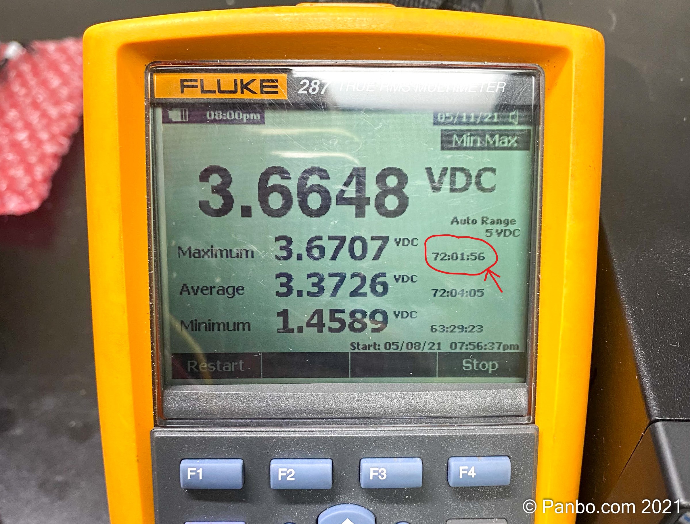
When I left you last, I was top-balancing the cells. This procedure brings all four cells to the same state of charge and gets them ready to be joined together as a 12-volt battery. Top-balancing connects all the cells in parallel which effectively creates a 1,120 amp hour (4 x 280 amp hour) 3.2 volt battery. For shipping, cells typically arrive charged below 50-percent state-of-charge (SOC) so, minimally you need to charge 560 amp hours of energy into them. With a 10-amp lab power supply set for 3.65 volts, I knew this was going to take a while. It wasn’t until the batteries had been charging for over 24 hours and only moved a few ten-thousandths of a volt that I did the math and realized it was likely to take two to three days. As you can see in the photo above, it took almost exactly 72 hours or three days to make it to my target charge.
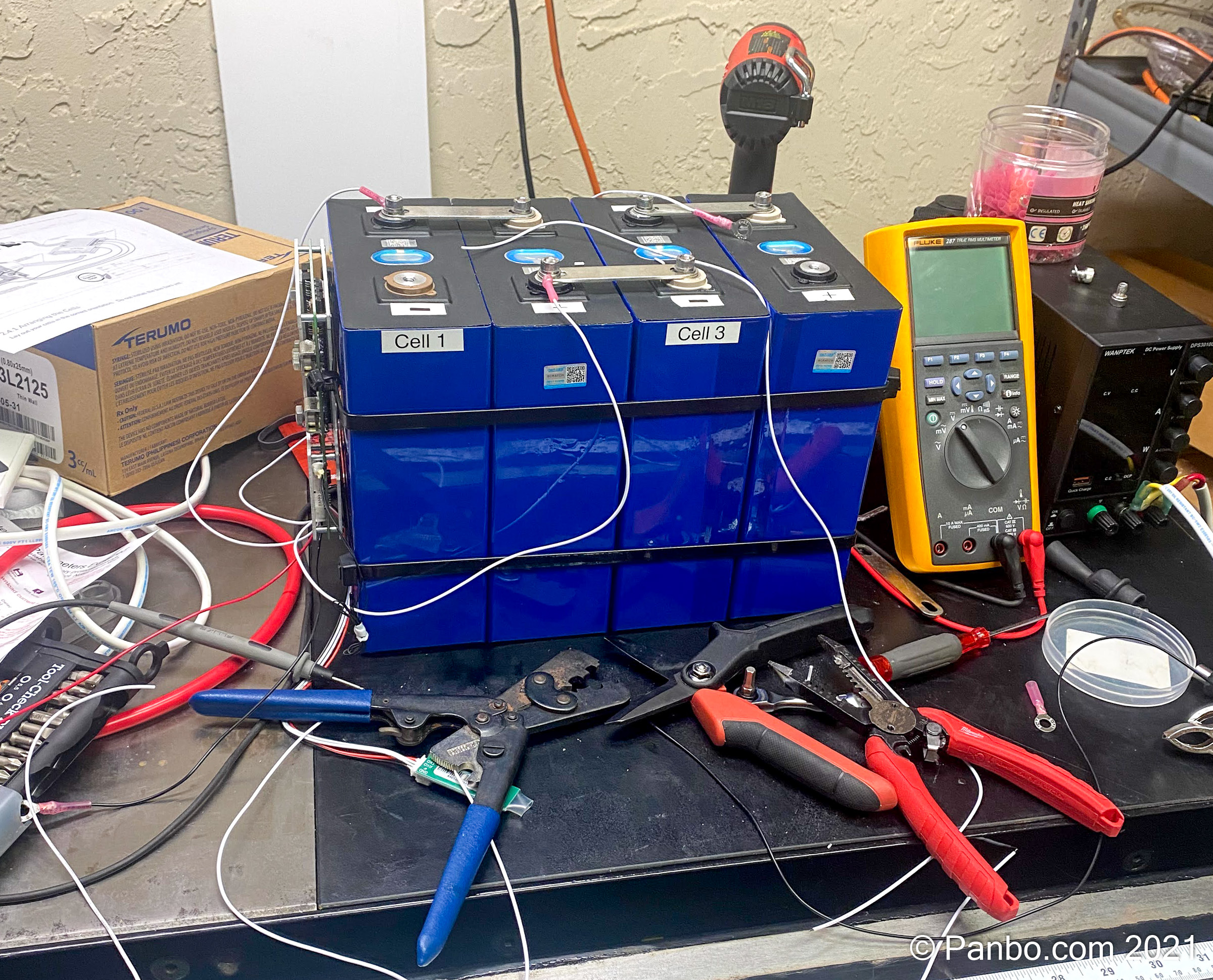
Next, I joined my freshly balanced cells into a four-cell serial configuration to make a 12-volt battery. I first joined the cells with the tin-plated copper bus bars on the cell posts and then used large zip-ties to strap around the batteries. The zip ties also give me an anchor point for the BMS, mounted to one end of the battery, and for the balance wires. As you may be able to see in the pictures, the cells aren’t perfectly regular, so there are bigger gaps between the cells than I would have liked.
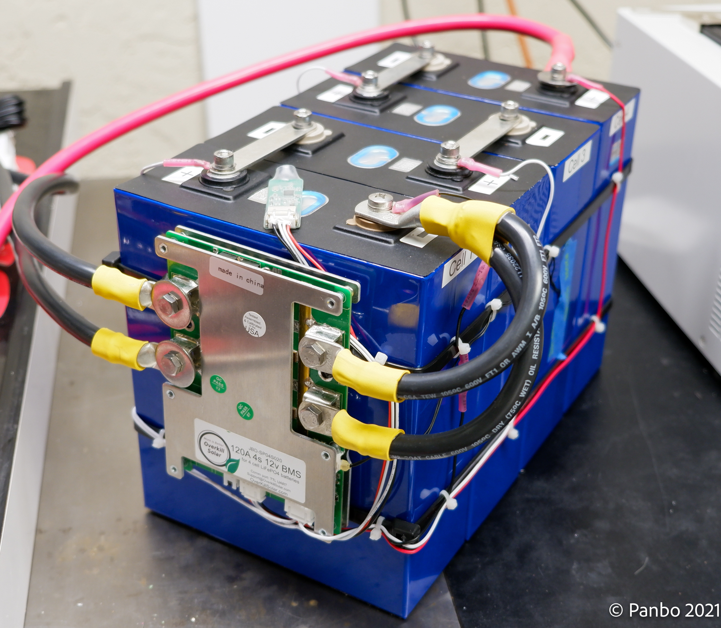
The final assembly of the battery consisted of connecting the BMS’ balancing leads to each cell and making cables to run from the negative post of the battery to the BMS and then from the BMS’ output posts to a bus-bar.
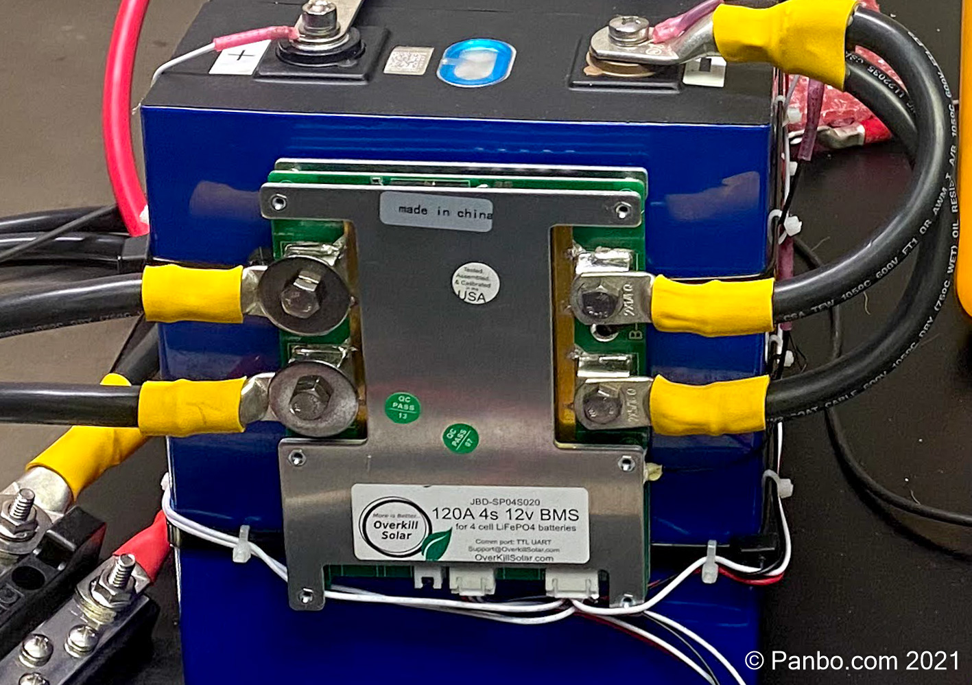
Overkill Solar’s 120-amp BMS can be ordered with M6 screw terminals or 8-gauge leads connected to the BMS; I got mine with M6 terminals. At best, 8-gauge wires run in free air can carry 65 amps at 75 degrees Celsius or below. With two wires in each running from the battery negative to the BMS and then two from the BMS to the load, this seemed a little close for comfort so I upsized. I only had 2-gauge wire on hand, so that’s what I used, but with a 170 amp-per-wire rating, it’s clearly overkill.
BMS configuration
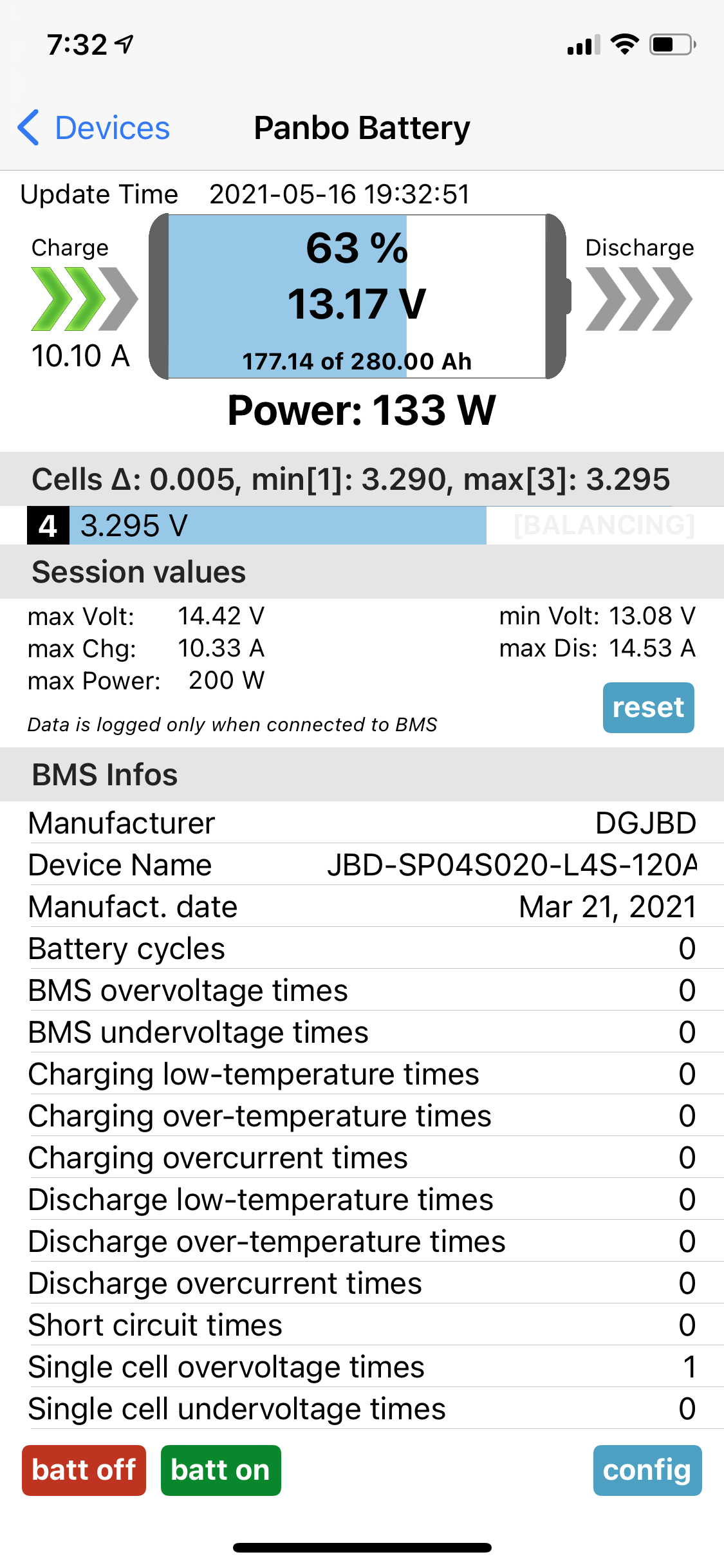
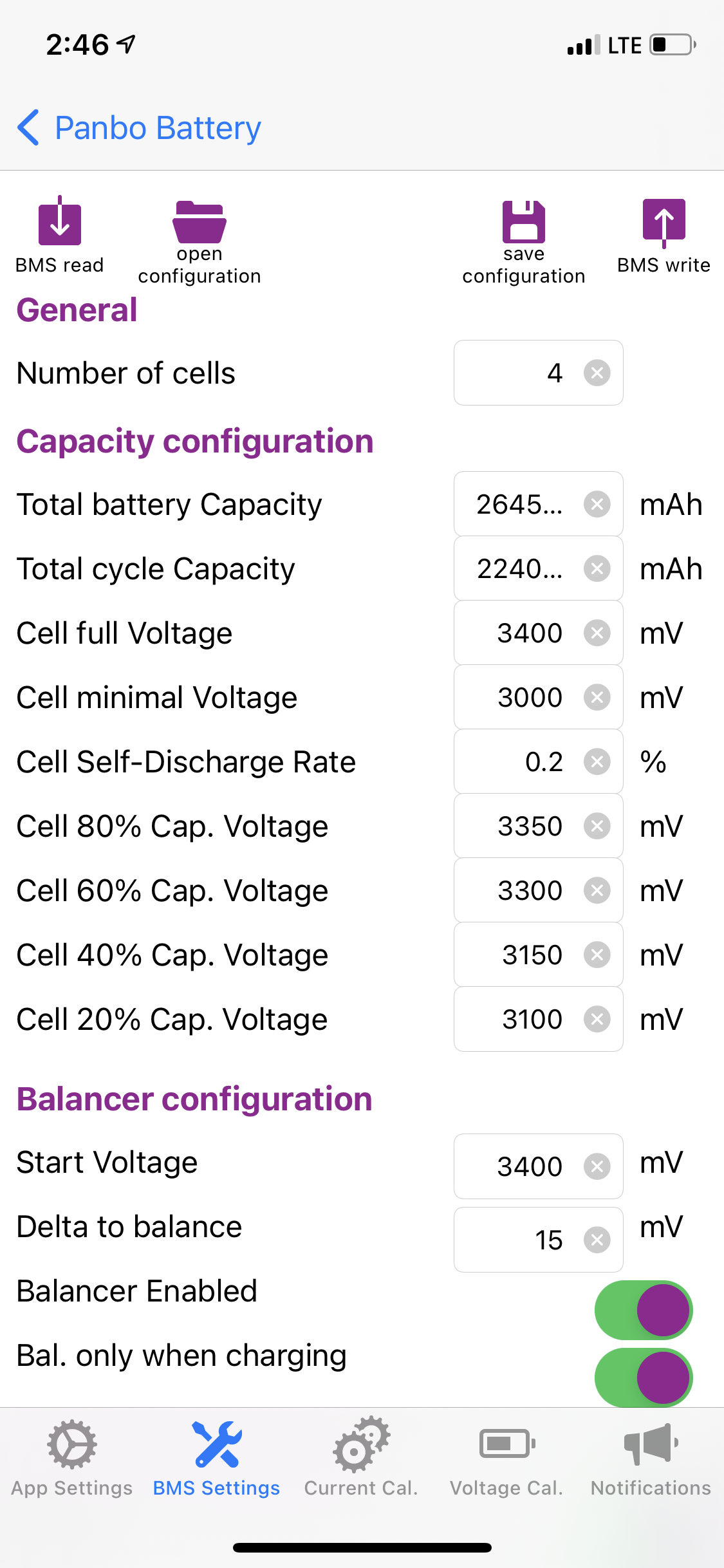
The BMS includes a Bluetooth transceiver for reading the status of and configuring the BMS. On iOS the XiaxiangBMS App presents a pretty nice visual representation of what’s happening in the battery and, with a $7 upgrade to the pro version, allows you to read the configuration from the BMS, change any values you’d like, and write them back. Considering the power and configurability of the BMS, I found it quite easy to work with. Plus Overkill Solar provides a great document that shows both the basic wiring of the BMS and their recommended values. It served as a cheat-sheet for me to get started with basic values. I tweaked a few of them based on my batteries’ capacity.
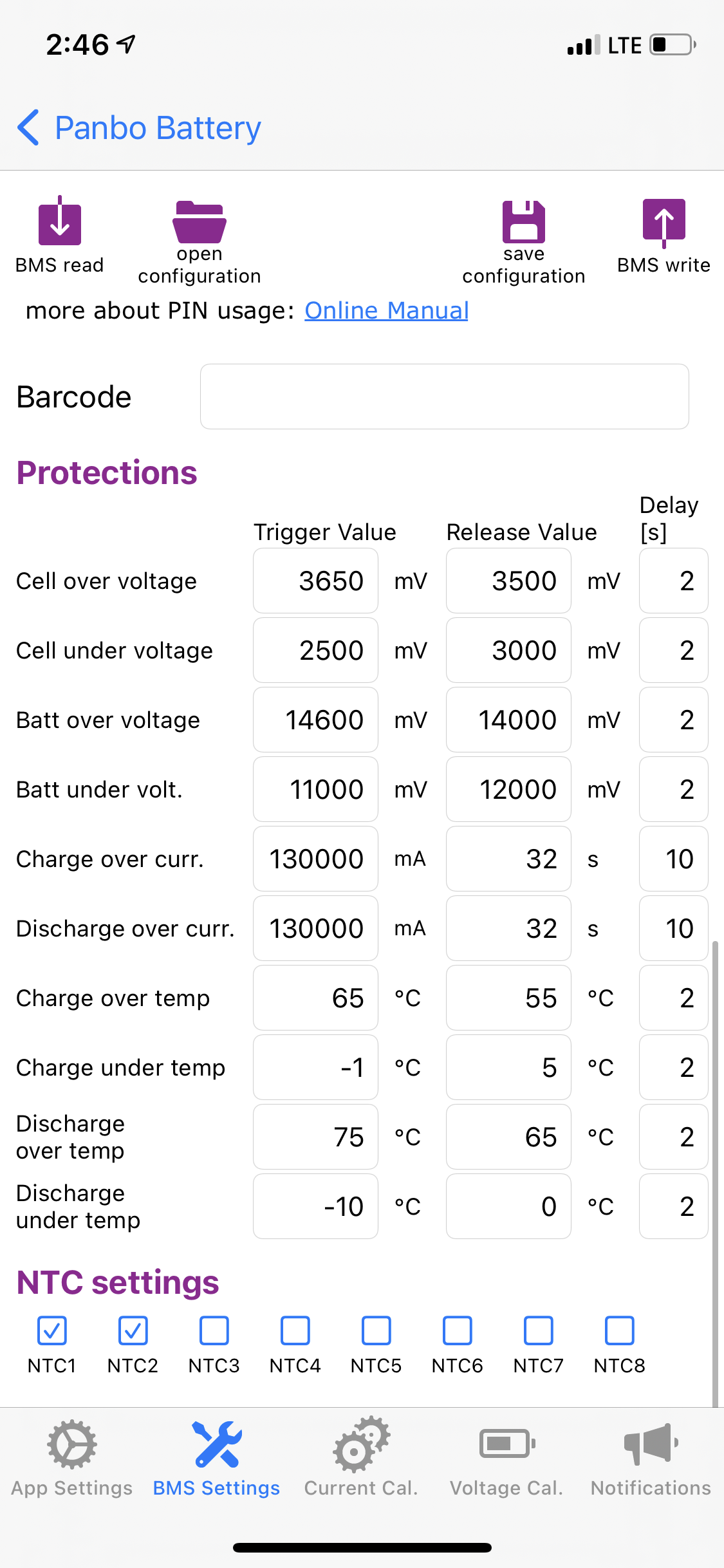
I was also able to test the BMS by setting some values intentionally low. For example, I set the discharge overcurrent threshold to 10 amps and then easily triggered it. I confirmed that after ten seconds over threshold, the BMS shut down discharge current and waited the 32 seconds it was programmed to wait before reactivating it.
Testing the battery
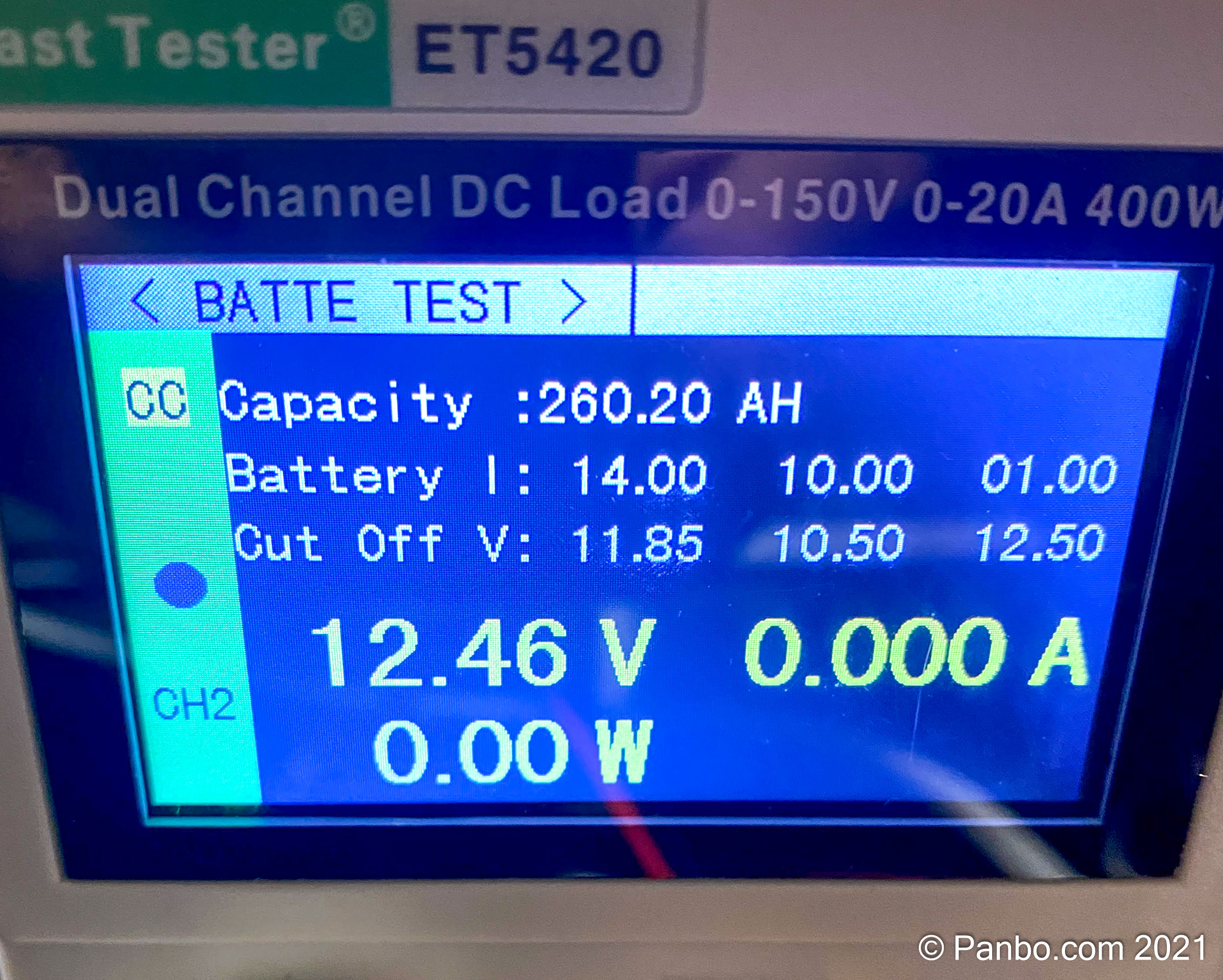
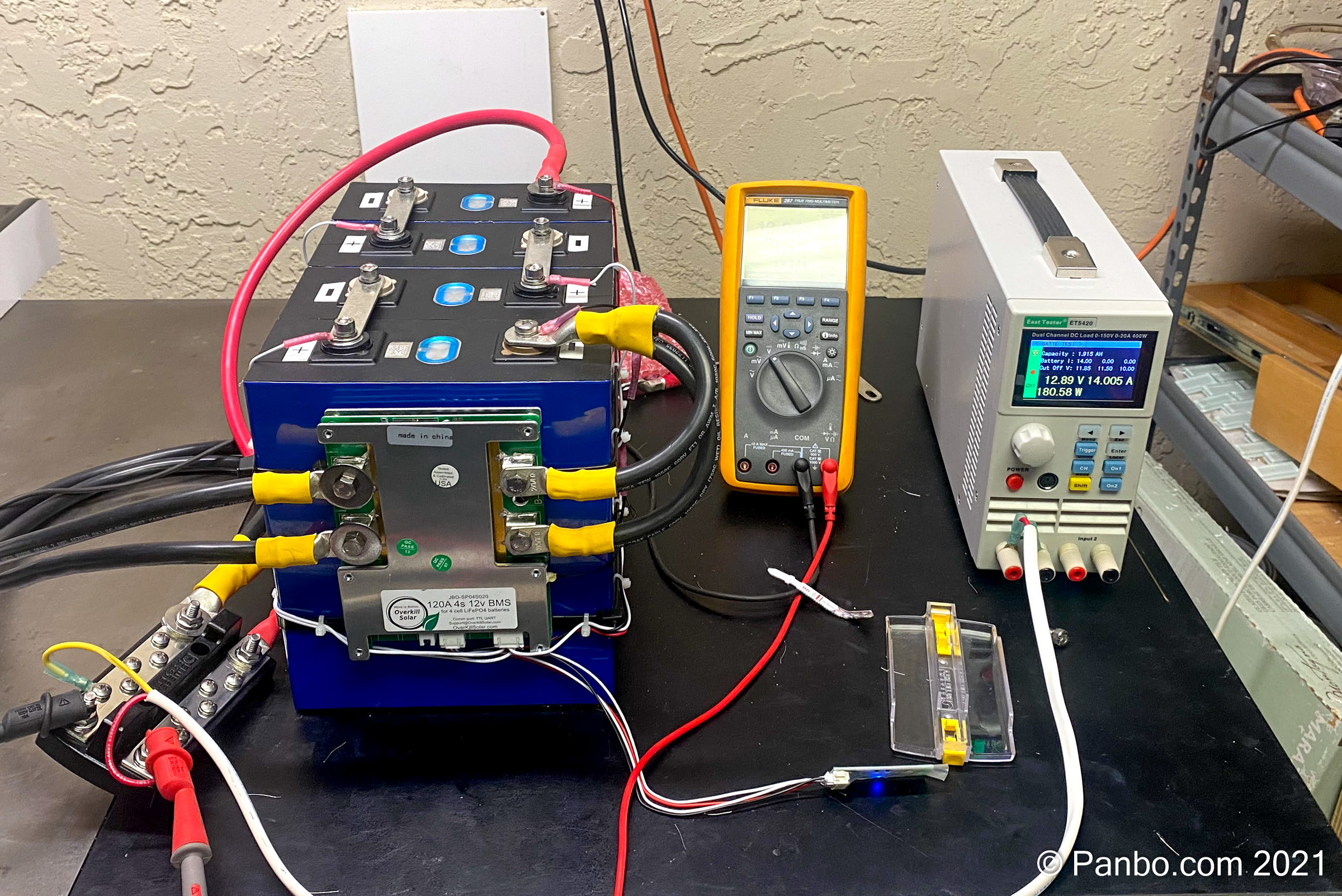
With the assembly of the battery complete I was anxious to answer the big question about my battery: Can a $600 battery, assembled on a workbench by an amateur, actually deliver 280 amp hours? I answered this question using an East Tester ET5420, an inexpensive (relatively speaking) electronic load. This device can place a consistent load on a battery and count how many amp hours the battery delivers. As you can see in the photograph above, the answer appears to be that yes, my battery can deliver nearly 280 amp hours of energy.
The picture above only shows 260.2 Ah, but this is easily explained. I chose to set the battery tester to stop its test when it reached a measured voltage of 11.85 volts from the battery. Because the tester is measuring battery voltage using the same wire that’s also drawing 14 amps from the batteries, there’s some voltage drop. In my testing I noticed about 0.3 volts, so the battery was probably at about 12.15 volts when the test was stopped. I’m in the middle of running another test with the cut-off voltage set lower, but I feel this test gave ample evidence the battery is capable of delivering 280 Ah. I’ll perform a further rundown test but I need a chunk of time when I can keep an eye on the test.
Comparing the results
| Maservolt Mli | Battle Born | DIY | |
| Nominal Voltage | 13.2 V | 13.2 V | 13.2 V |
| Battery capcity | 400 Ah | 270 Ah | 280 Ah |
| Cycle Life | 3500 cycles @ 80% DoD | 3000-5000 cycles | 4000 cycles @ 80% DoD |
| Max continuous discharge | 500 A | 300 A | 130 A (BMS Limited, cells support 280 A) |
| Peak discharge current | 1800 A (10 seconds) | 500 A (30 seconds) | ??? (over current shutoff after 10s) |
| Continuous charge current | 200 A | ??? | 130 A (BMS Limited, cells support 140 A) |
Having recently worked with both Mastervolt system integrated LiFePO4 batteries and BattleBorn drop-ins, I was impressed at how similarly this battery performed. I saw the same voltage stability, even under heavy loads, that I saw with the other batteries, the same charge acceptance characteristics and generally didn’t feel like I was giving up performance compared to the more expensive batteries.
I do feel that, at least compared to the Mastervolt MLi batteries (and probably Victron’s as well), I am giving up the ability of the batteries to communicate with other components in the DC system. That communication, which I covered in my in-depth review of the MLi batteries, means the batteries can communicate with charge sources and loads to request they stop charging or warn of an impending shutdown. There are other ways around this potential problem, like a Sterling Alternator Protection Device, but none as elegant as a single communications bus for all the DC equipment.
When compared to the Battleborn or other drop-in batteries, I think the ability to monitor and configure the behavior of the battery is a real upgrade. With the vast majority of drop-in batteries there’s simply no communication out of the battery. So, you’re on your own to figure out why a shutdown occurred or monitor the health of the battery.
Now let’s talk about cost for a minute. My four 280 Ah cells were $471.42 and the BMS was $132.00 for a total cost of $603.42. I also used quite a few crimp terminals, battery cable, and lugs but those were all from supplies I had on hand so I’ll estimate the cost of those supplies at $30. Lastly, I used quite a few tools I already own like terminal crimpers, battery lug crimpers, bench power supplies, battery tester, and multi-meter. I’ve previously discussed the many variables in comparing the cost of LiFePO4 batteries and flooded lead-acid (FLA). Those comparisons were done using a Battle Born 100 Ah battery that cost $900 or $9/ Ah. But my 280 Ah battery cost roughly $633 or $2.26 per amp hour. In my analysis, LiFePO4’s economics only really got favorable when compared over the expected life of both batteries. But, at less than one-third the cost of the Battle Born, my DIY becomes cost-competitive much sooner.
Final thoughts
Should we all dump all name brand batteries and just make our own? I don’t think so. I don’t think we should undervalue the expertise of manufacturers who engineer, build, and support these batteries. They ensure they are safe for all users and protect you from the many potential pitfalls of building your own. But, if you’re on a budget, have the skills, and can manage the safety issues I think they’re a heck of an option. I’ll also tell you I’ve had a lot of fun researching, learning about, and ultimately building my battery. I’m seriously considering upgrading my RV to LiFePO4 with two of these batteries. If I do, I’ll want to figure out a nice and well protected enclosure for the battery, but that might be as simple as a group 31 battery box.


as always .. informative, well researched and presented.
your results appear consistent with a number of “internet/youtube” blogs covering DIY LiFePo4 battery builds for solar/off grid and Rv applications – so great to see more validation from a marine perspective.
the “cost” comparisons are not suprising … as i guess you have to factor
– the time/cost of your own labour (if we added that up, we would never do it based on $ economics, but where would the fun be in that!)
– commercial companies have to carry warranty and various obligations
– they are in business to generate margins and profit
… however i do believe this demonstrates that a number of companies are “profiting” from the
early adoptor/leadership phase ,
– lets be realistic, none of the mentioned companies “manufacture cells” … they assemble a finished battery .. from bought in components, in partic the cells..
– which almost certainly share commonality with the DIY sources, albeit the commercial,entities demand and expect higher quality control and specs.
– at present .. with limited competition.. consistent with early phases of “new” technology introduction and adoption, the prices are still “high” for commercial solutions..
… we are certainly on the “cusp” of increased volume. innovation, consumerisation and competition in the battery space… which can only drive the $/energy downwards.
… there is always a “cost” to be an innovator, but you have demonstrated that with modest tools, research and learning, you can deliver a safe and VERY cost effective result with “DIY” expertise.
keep up the great work.
Greg,
First, I think this may be the nicest comment I’ve ever received on an article, so I really appreciate that. It’s rewarding to know our readers find value in what we produce.
I agree with your analysis entirely. I should have at least mentioned the value of my time because you’re right, it’s a real factor.
-Ben S.
one thing i noted from your build…
there is a growing consensus in other “spaces” that some type of cell “compression” can be beneficial for longevity .. there are (as always) lots of opinions on how and how much…
.. but i dont think “cable ties” deliver the type of compression that seems more typical…
and of course a marine environment is a lot more severe than “off grid and RV banks”.. for vibration and movement.
… you may want to look at that as part of your “battery box” enclosure
I’ve been thinking about doing just that. I really like the basic frame that Overkill was making for their 100 Ah batteries (https://overkillsolar.com/product/frame1/). They’re not making it any more and it wouldn’t be the right dimensions for my 280 Ah cells but I’m trying to figure out what I could as end plates for a very similar and simple compression enclosure.
-Ben S.
Find someone with a 3D printer and have them print you two end plates taht that fit your batteries exactly.. Looks like the two end are held together with some threaded rod..that doesn’t look too hard to make.
ABS or ASA should do nicely. for end plates and it will be just as sturdy and lighter than the metal ones from overkillsolar.
I think those end plates are going to end up being under a lot of stress. I could make them with Starboard or something similar but I worry that I need metal. The other option I’m considering is making them out of Starboard and then using a couple of inch long backing plates to spread the force over the Starboard.
-Ben S.
It would seem a couple of thick aluminum plates could work. You can work aluminum with wood working tools but it makes a bit of a mess.
Nice reading material, I can learn a lot of it.
I am still doubting between a DIY or Mastervolt MLI. Mainly because the communication issue, which you mentioned.
If I can source a BMS with NMEA2000 communication, it will be a DIY. But until now I did not succeed in finding one.
Only alternative (in my case), is the Mastervolt MLI (I have Mastervolt / Masterbus installed already).
Agreed that it would be magical if we could find a BMS with N2K. There’s a guy who works for Maretron who is building a bunch of DIY batteries for his own boat. He’s been talking about creating an N2K bridge for the Overkill BMS using the UART interface. I’m not sure how far he’s made it. I’ll check in with him. That would be the holy grail if we it comes to fruition.
-Ben S.
I found something via the https://marinehowto.com/ site you referred to:
Orion BMS 2. This unit has 2 canbus connections.
Yacht Devices has published a method to convert this canbus to NMEA2000:
https://www.yachtd.com/news/orion_bms2.html
This would work, in my opinion. But will take a lot of work.
I was also checking pricing of the MLI (24/5500) compared to DIY solutions. The Orion BMS 2 costs about € 1000,= here in Europe. And a 400Ah 24V DIY costs about € 3000,=. In total about € 4000,= excluding the programming which have to be done.
A MLI 24/5500 costs around € 6.000,=, about 1,5 times more.
But is only 200Ah. thus the MLI is 3 times more expensive.
That is a big difference.
My comment was gone:
I found a Orion BMS 2 with canbus, via the https://marinehowto.com/ you linked to.
The NMEA 2000 Bridge YDNB-07 is able to convert the canbus to NMEA2000 messages:
https://www.yachtd.com/news/orion_bms2.html
It should be possible to do a DIY battery with NMEA2000 connection.
DALY makes a smart BMS with CAN bus connection (dongle). I have not tried this yet, but it appears that the DALY BMS follows the RV-C can bus protocol. It should not be that difficult to make a bridge, or even find CAN bus enabled inverters/chargers.. Not sure if victron understands RV-C, but that would be amazing.. I have more research to do.. I jsut dropped new FLA bateries in last year, so I have 2-3 years to go before my next replacement, and I want to be ready. I really like the DIY batteries. I wonder if something special is needed to keep multiple 12V 280Ah batteries balanced when they are in parralel.. it would not be too expensive to build a battery bank with 1120 Ah. That’s 13.4kWh.. Enough to run my A/C overnight and then some 🙂
I can dream …
I don’t personally quite see the need, why do I really need this info on N2K when I can read it directly from BMS or over the network/BT whatever?
But if you really want this, it is easy to DIY.
First, pick a good BMS. Electrodacus is nice, communicates standard over IP on wifi.
Then either hook a arduino with canbus shield or a raspberry and usb/n2k -converter to BMS, and you have it.
Literally few tens of lines of code, to make the bridging.
And speaking of BMS, I would most definitely consider a BMS of “offline” topology. Ie. one where the current does not go through the BMS, and the BMS can be removed/replaced without affecting the power delivery.
Electrodacus I mentioned is nice, there are others.
One question:
Like most DIY I see, the BMS wiring is not fused. Worst case, a shortcut causes overheating and fire of those wires. Any battery can supply enough current to overhead and melt small wires.
(As these are small wires, maybe they behave as a fuse themselves.)
How is this addressed?
How do you see this?
I have a couple of thoughts on that. First, with the battery well protected by an enclosure, the chance of compromise of the conductor should be quite low. Second, I do think the wires will behave as a fuse if there’s a dead short.
Along the lines of thinking about risk, ABYC E11.10.1.1.1 states that pigtails less than 7 inches are exempt from overcurrent protection requirements. I’ll admit I didn’t measure the positive balance lead, but it’s darn close to 7 inches.
-Ben S.
This Orion BMS I mentioned in the previous reply has fused balancing wires.
Ben, Love it. Will the BMS also provide individual cell voltage for tracking drift? beyond just the balancing delta? I had to manually measure ours with my Fluke DMM. I found the variations required measuring to thousands of millivolts for accurate tracking something that less expensive testers cannot display. All in all, well done!!!
Joe,
The BMS does indeed provide individual cell voltage as well as data on what it’s doing to balance them, when it’s balancing. This BMS, like most I’ve looked at, only balances at the top of the charge cycle. So far, I’ve seen very small cell deltas, usually around 0.005 V or less until the very end of
charging, which makes me quite happy.
-Ben S.
Ben S.
Thank you for diving into this topic with both feet. Between the two Ben’s we should gain perspectives unavailable otherwise, no matter how we research individual offerings.
Is there a way to evaluate how conservative the Overkill BMS is when it comes to charging/discharging limits?
Thanks again!
Don
Great question about the limits of the Overkill BMS. So far, I haven’t been able to do too much testing of the limits because my load capabilities are limited to about 30 amps using the digital load I have here.
I’m considering installing this battery alongside one more on my RV which would give me the ability to load it up a little more. I’ll report back as I do that.
-Ben S.
A 20 amp inverter draws around 250 amps. The DIY battery will barely support that even at full rating. Momentary motor startup current is substantially higher. Even the Mastervolt battery system will barely support their new 3000 watt inverter-charger.
The MLI are rated 500A continous discharge.
I’m a little unsure what you mean by a 20 amp inverter drawing 250 amps. I think there are some units missing there. I’m guessing you mean a 20 amp AC inverter draws around 250 amps DC at peak?
Assuming that’s what your saying, you raise the valid point that the battery and its components must be sized for the intended use. I didn’t build this battery intending for one of them to power a multi-kilowatt inverter. I may well do that with two or three of these batteries, which I don’t expect any trouble doing. 120 amps * 13 volts = 1,560 watts per battery. That means two of them can produce 3,120 watts continuously and more for short periods of time. That’s plenty for my applications. I felt 120 amps continuous is plenty for a battery with a 280 amp hour total capacity (224 aH at 80% DoD) since that would mean fully draining the battery in two hours. I wouldn’t size a battery bank to be depleted that quickly so 120 amps of draw capacity per 224 useable amp hours works for me.
-Ben S.
Does your BMS have a way to limit charge to 50%? Your batteries arrived at 50% charge because that is the recommended level for long term storage of this battery chemistry. My electric car has the same recommendation to always store at 40 to 60% charge.
Storing at 50% so far for the car has been more of a nuisance than a problem.
Ben,
Thanks for the write-up! Awesome job of informing those of us drooling over LifePo but waiting to pull the trigger.
Am I correct that the Victron BMS only works with their batteries? I’ve got Victron solar controllers and would like to sty within their eco-system.
Have you looked at the REC BMS. One of its firmware’s is reported to integrate with victron’s CAN bus, which might solve the system integration problem for DIY batteries. I think I’m heading MLI, because of my existing investment in mastervolt kit.
No, but I’ll go take a look now.
-Ben S.
Thanl you for mentioning the REC BMS. I had not heard of them before. I was looking for something exactly like that. Glad someone had already figured it all out so I don’t have to 🙂
Great build. I just build and installed nearly the identical setup w/ a battery box completed with a breaker and LFP is a game changer for me.
While the BMS provides over current protection it’s nice to have a backup with a std fuse or breaker that also doubles as an on/off switch at the battery. It does take some time to learn (many builds found on the internet) and go slowly the first time but I would think my 2nd build could be done with only a couple of my time. My biggest issue was waiting for the cells to arrive from China wondering about my Alibaba supplier – which turned out to be just fine.
Couple thoughts:
The M6 terminal on these cells are shallow and can be stripped if the bolts are not the perfect length. Many have, including myself, have opted for studs (that have hex key at the end) w/ nuts so they can grab all the threads available (or avoid the dreaded bottoming out) while putting zero torque on the terminals..
To speed up top balancing first connect the BMS and charge to 14.5 or so (one cell will likely stop the process before then) which gets you 95%+ there. Then w/ cells in parallel slowly top off at 3.65.
Re: compression, the aluminum cases provide some (enough? debated it seems) but I’ve used several wraps of fiberglass packing tape and shims in my box provides some as well. I think my batteries will calendar age out (or replace w/ better tech) in 10+ years before they loose much capacity. I figure the same goes for keeping them topped off / stored at full SOC. I split the difference and keep mine at 80-90% and I’ll top off a few times/yr (Note: Battleborn says it doesn’t hurt their batteries to keep at 100% SOC, they recommend hitting 100% to make sure they balancing happens) Battery is only as strong as its weakest cell.
Final thought, if you like a project like this switching to lithium/LFP is night and day from SLA but don’t forget some attention to the charging side / watch the alternator temps. Can’t go wrong with Battleborn or even something from bigbattery or SOK if you want something to drop in and go.
David,
As soon as you mentioned the idea of using studs instead of screws or bolts in the (weak) threads of the batteries I went looking for some. I’m able to find plenty of metric set screws that will work well, but I can only find them in stainless. I’ve always worked to avoid the use of stainless hardware in the current path of batteries because of its lower conductivity. Did you find any other materials for the rod or screws?
-Ben S.
You could get adventurous and make your own.. All you need is some metric round stock (Steel, copper, whatever) and the appropriate die.. The studs are relatively short so they are easy to make. It’s just time consuming.
Another great article Ben, with well communicated context — thanks! I built a 200Ah array using the same type of cells you have, and a Daly BMS. This past long weekend was my first use of it in our camper. Comparatively speaking, I went to 2/3 the size, 1/3 the weight and 5x the longevity between charges in a $450 total cost battery.
It would be great if you could do an article on the setup of these common 280Ah cells in a 840 or 1120Ah 12v house bank setup for boating. This is where my head goes for my boat, but I haven’t yet gotten my head around how a BMS (or multiple BMS’s) would work in that case.
I think the multiple BMS point is key for marine use. FLA batteries fail relatively gracefully, but a failure of an LiFePO4 battery will result in the BMS isolating it, which is a very good thing given the amount of energy stored. However at sea I want a resilient and redundant power supply: I don’t want to lose my instrument systems, powered fresh water pumps, electric bilge pumps, and lighting all at once if the BMS detects a fault. If (when) I move my boat to LiFePO4 there will be multiple batteries each with their own BMS. It will cost more, but should mean that I’m less likely to be unexpectedly plunged into a total blackout.
Having two batteries adds a few problems I would like to see the BMS address before having my power system be based on two of these. Otherwise the best 2nd battery, may just be a lead-acid one.
* Provide the user with an audible alarm. Currently, the Overkill BMS does not have this. If this is your only battery, total lights out is a good enough indicator.
* BMS’s monitor each other and alarm. My understanding is that many users with dual batteries put them in parallel. In a multi-battery situation, one battery going off-line will go unnoticed. If the BMS can monitor another BMS, it can alarm on it’s behalf.
* Sometimes your 2nd battery is a lead-acid, ideally in that situation, you can strap the identical model BMS to your lead-acid battery and have it work in a mode that it provides stripped down functionality to monitor your lead-acid battery and alarm on problems with the BMS connected to your LiFePO4
* Expanding on the feature that the BMS will shut down your batteries before they run below the point they can be safely charged. make the BMS programmable to the amount of power you need to start your engine and monitor that there is enough power across your available batteries to start your engine. Then alarm first, and later trip off the power in a way that leaves you available power to start your engine.
IMHO
The Overkill BMS has some really good features. Insist that your choice of BMS have them also, the above dual battery dream features are additive.
A good BMS monitors and gives warnings and alerts. If ignored, a fatal event can cause the shutdown of the lithium battery.
Same way a FLA can shortcut internally, if a user does ignore the warnings.
Main difference is, we are used to FLA batteries and know how they behave, and see the warnings (or as you called it, gracefully fails). Lithium behaves different, and yes, this takes extra attention to get used to.
One battery is always a single point of faillure, either FLA or Lithium.
Absolutely agree. The key things for me are BMSs ought to play nicely with each other (as we will all need more than one), and we need to get used to thinking of a BMS and cells as a battery. As you say we all have redundancy in our FLA systems, there’s a risk that it’s lots in a move to LiFeP04 through people choosing to have a single BMS.
* it’s lost in a move… above.
Ben
The DIY solution does present some strong reasons for the DIY LIPO install but one thing still has me wondering if LIPOs are a wise choice.
I have read several articles about LIPO batteries that raises the issue of a “dark ship” condition that would occur with the BMS shutting down the batteries. There has been suggestions of adding lead acid batteries into the system to supply power during disconnect occurrences. But that seems counter to the premise of the LIPO batteries -though the logic of this solution was rationalized rather well.
Since you reference the need to protect the alternators in case of shut down it seems that a disconnect occurrence is to be expected at some point. If so it seems to me that this could present a substantial problem with LIPOs.
Can you (or anyone else) comment on your thoughts about this issue?
2 thoughts:
1. As written before a BMS should give wernings before shutdown. You can take actions to prevent a shutdown.
2. There are multiple BMS (Victron, 123 for example) which have 2 protection options, change and load. To prevent overcharge, the charge relay can shutdown, but your load will be powered still via the load relay.
As Wolfgang mentioned, several BMS can shut down charge and discharge separately. So, if a cell is going overvoltage just charging can be shut down. The Overkill BMS I’m using does just this.
Additionally, although it’s prudent to design for a shutdown these shutdowns shouldn’t occur in normal operation. Shutdowns occur when something goes out of spec on the battery to a degree that the BMS needs to step in and protect the cells.
Lastly, multiple batteries provide further protection from a dark-ship scenario. Unless something occurs to take out all the batteries in the bank you’ve got good redundancy from the multiple batteries. It’s still a little bit early days for my installations so I haven’t seen a shutdown event and certainly hope I won’t for quite some time. On the other hand, I’ve run lead-acid batteries for many years and have seen several failures in those some of which left the bank dead.
Each system comes with tradeoffs. One of the tradeoffs for BMS protected LiFePO4 batteries is that they’re better instrumented and protected. If you take advantage of the instrumentation to monitor the health of the batteries, hopefully, you won’t ever experience the effects of their protection measures.
-Ben S.
Thanks Ben
Good explanation – and seems like rational approach.
I’ve just built a 660Ah 24V bank for our boat out of individual cells and used the Emus BMS (emusbms.com) which hooks nicely into our Victron system and onward from there (WS500 to victron works as well). They have several systems and I found the balance boards to work best. Can be extended to any size battey bank and runs very reliable. Looked i to all the other BMSs and couldn’t find any that supports multiple parallel strings and has a CAN bus interface
Lenz,
I’m curious what portion of your build expense ended up being the BMS. I’ve looked at some really lovely BMS architectures but in all cases, the cost of the BMS has met or exceeded the cost of the cells. Part of what’s so attractive about a $100ish dollar BMS is that it keeps the total expense of the battery reasonable.
I’d love something more advanced, something that’s not in the critical path, etc. but at $300+ it defeats some of the cost-effectiveness of a DIY solution.
-Ben S.
Thanks for the directions to this BMS, I did not know this one.
From memory one balance board is around 15EUR a cell module controller around 60EUR and the main controller around 350EUR. For a larger bank that starts to work out as you only need more balance boards and one cell controler per pack (4 or 8 cells depending on 12 or 24v) and for smaller builds (one string) they have the mini which i have no pricing for. Yes BMSs are expensive but this one is cheaper and better than Orion and REC from what i found out anyway … happy to hear other opinions from people who built packs with other BMSs, not too much info out there unfortunately 🙂
If you want to get more information regarding lithium battery systems for marine, check out this blog:
http://nordkyndesign.com/category/marine-engineering/electrical/lithium-battery-systems/
MarineHowTo also refers to this blog.
There is lots of useful information to gather from.
hi, i am also seriously consider building my own lifePO4 battery for my new boat, my idea is to use twin battery system, 1 lead acid batttery for cranking and a LifePo4 for house. WIth a isolator switch to isolate both circutries such that they don’t mixed together. I am also very much to know if i can use LifePO4 for my RV as the main battery?
Hi Ben, I am curious if you have any update on this after a year of operation. Do you still feel that “But, if you’re on a budget, have the skills, and can manage the safety issues I think they’re a heck of an option”? Also curious if you have found anything that addresses the communications issues that you pointed out. thanks!