
Where’d the watts go? Inverter/charger conversion losses mount up
I’m getting Have Another Day ready for a pretty major upgrade from her current flooded lead-acid GC2 golf cart batteries to a MasterVolt LiFePo4 lithium iron house bank. There were a few surprises along the way — including this weekend’s discovery that four of the recently checked GC2 batteries were nearly bone dry — but the one I’d like to discuss today is the large apparent conversion loss just found in my boat’s 18-year-old DC system and specifically the inverter/charger.
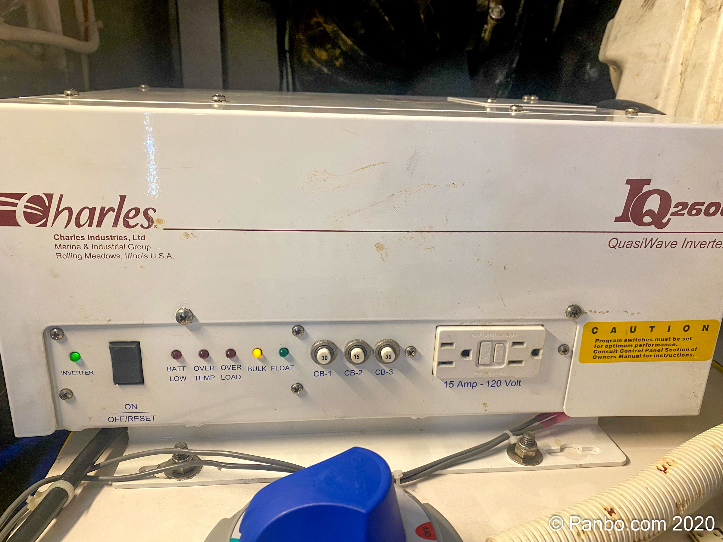
Preparing for the lithium house bank requires replacing the Charles Industries 2600 Watt quasi sine-wave inverter/charger with a new MasterVolt CombiMaster 3000 watt true sine-wave unit. The Charles (actually made by Vanner and still available today) was original equipment on the boat when it was built in late 2002. So, it’s lived a good life and given me a lot of good service, however, since it doesn’t have LiFePo4 charge profiles it’s time for an update. But, before I removed the inverter I added some metering around it so I could understand how it was performing and then compare it to the CombiMaster.
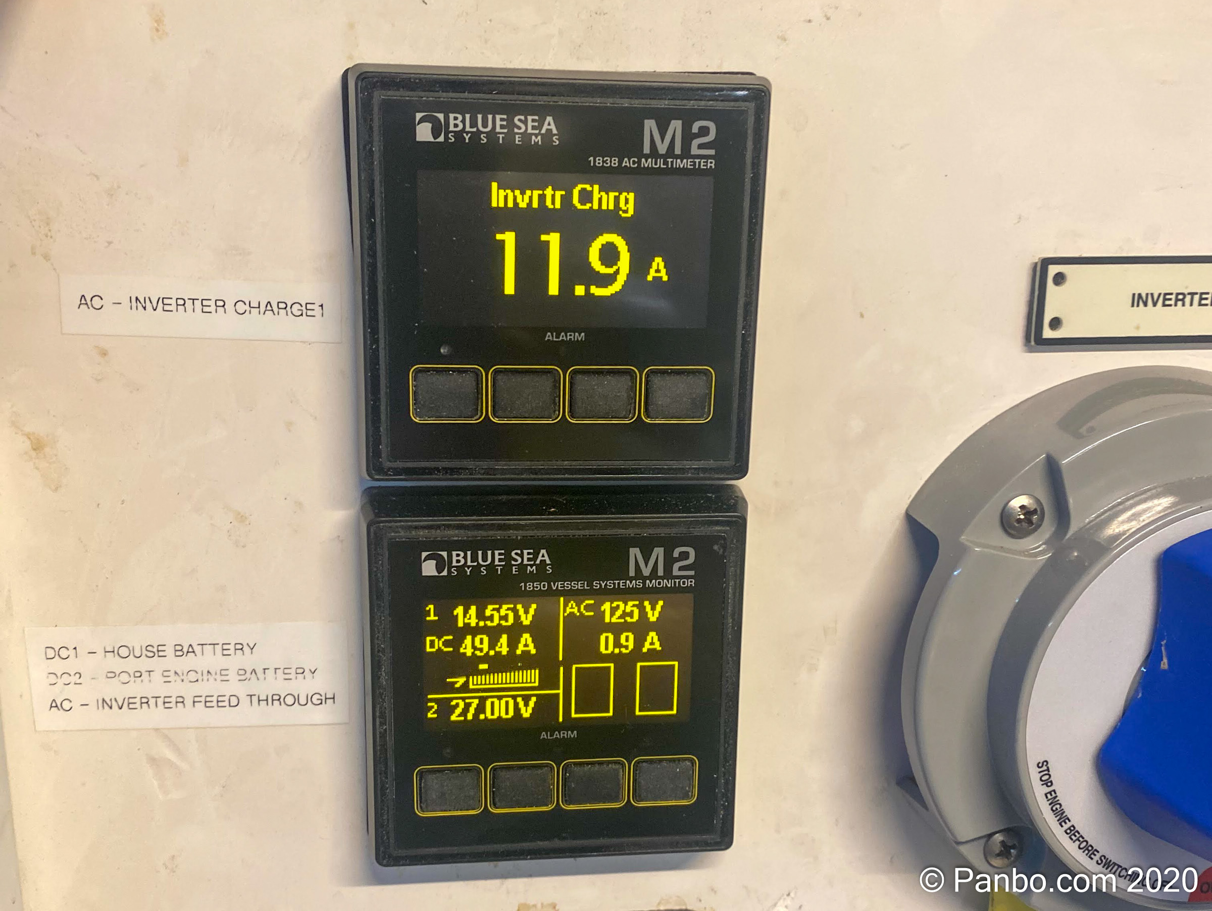
But, before I got the chance to compare the results between new and old inverter I found a surprising amount of electricity seemingly missing. As part of my DC refit project, I added the two meters in the pictures above to better understand power in and out of the inverter/charger. The top, Blue Sea Systems 1838 AC Multimeter, is being used to monitor the current going into the charge input of the inverter. The bottom, Blue Sea Systems 1850 Vessel Systems Monitor, is monitoring the feed through input of the inverter as well as the voltage and current consumption of the battery bank attached to the inverter.
You might be wondering why there are two AC inputs on the inverter/charger. For inverter only models, there was only one input, for inverter/charger models a second (optional) input is added. The second input is a dedicated charger input.
What we see in the photograph above is that the inverter’s charge circuit is consuming 11.9 amps of AC power. Anytime you’re comparing electrical readings of different voltages it’s helpful to convert everything to watts because one amp at 12 volts isn’t the same as 1 amp at 120 volts, but one watt is always one watt. To do that, we multiply amps (11.9) times volts (125 as can be seen on the right side of the bottom meter) to arrive at 11.9×125 = 1,487.5 watts. So, that means the inverter is consuming just under 1,500 watts to produce 49.4 amps of DC power. We can see on the left side of the bottom meter that 49.4 amps of DC current is going out the inverter’s DC output at 14.55 volts. To convert this to watts we will again multiply amps by volts or 49.4×14.55 = 718.77 watts.
In summary, that means the inverter is drawing roughly 1.5 kilowatts to produce roughly .7 kilowatts of DC power. Doing the subtraction shows that we’re losing 768 watts somewhere. But where did that power go?
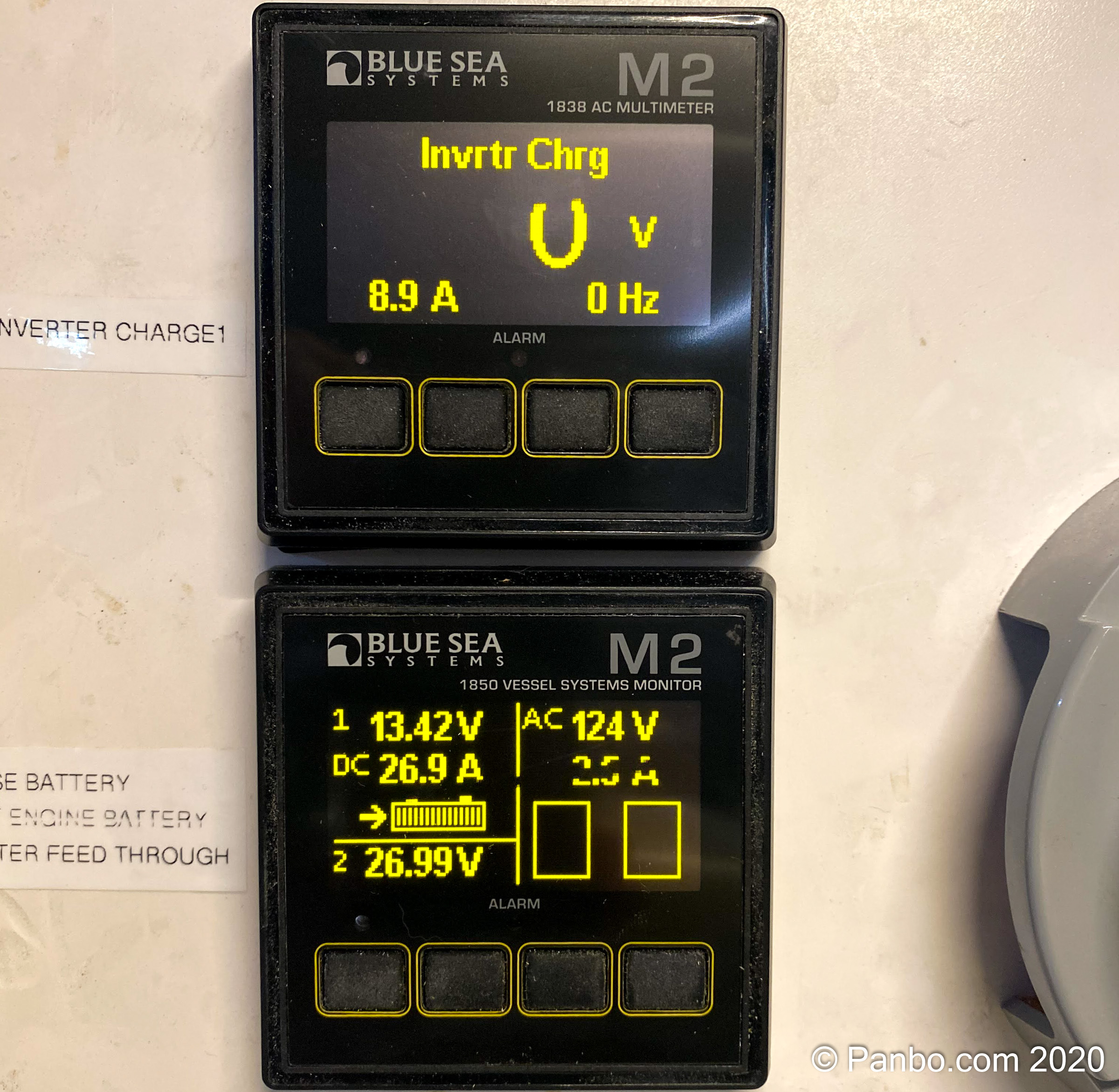
Could this be right? Is the inverter really wasting 700+ watts of power? Well, I checked again after letting the batteries charge back up to see if the losses might decline. Maybe the amount of loss is a function of how much charge is being generated, right? This time we have 8.9 amps coming in at 124 volts for 8.9×124 = 1,103.6 watts and we’re outputting 26.9 amps at 13.42 volts for 26.9×13.42 = 361 watts. 1103.6 minus 361 is 742.6 watts of power lost. So, that’s pretty darn close to the 768 we saw in the first calculation. So, no, it doesn’t look like loss is a function of how much charging we’re doing.
But really, where is all that power going? The short answer is, I don’t know. I suspect much of it is going to heat. The cooling fan almost always runs on the inverter but, damn, 750 watts of heat is a lot of heat. Take a typical 1,500 watt space heater on half power and that’s how much heat we’re talking about. I’m surprised I hadn’t noticed this before.
Now, let’s look at that roughly 750 watts of power from a financial perspective. I’ve previously whined about my electric bills and this might help explain some of this. I currently pay $0.14 per kilowatt hour of electricity; 750 watts is .75 kilowatts, and if we assume we’re wasting .75 kilowatts 24 hours a day that’s 24x.75 or 18 kilowatts a day wasted. At $0.14 per kilowatt that’s $2.52 a day in wasted electricity or $78.12 in a 31 day month wasted or $919.80 in a year. That’s real money! If the new inverter is more efficient it’s likely it will save more than it costs in a little over a year just from less waste.
Now, dear readers, let me ask you what I’ve missed? Is there somewhere else the power is going? Some factor I haven’t considered or a logical detour I’ve taken? I’d love to hear if others are surprised by the amount of waste or if this is a well known fact I’ve just missed. I fully expect there will be conversion losses as we move from 120 volts to 12 or vice-versa, but not on the scale I’m seeing.
Next up on my installs will be the new CombiMaster inverter and its control system. Once that’s installed, I’ll have a better idea of the savings I might get from a newer, more efficient inverter.


I’d check that your AC and DC ammeter scaling are set properly for the current transformers & shunts you’re using.
Sorry, I should have mentioned that I did check all the Blue Sea meters off of my existing meter and found the results to be extremely close.
-Ben S.
FYI, the Vanner documentation lists the two AC inputs as feedthrough only and charger + feedthrough. There is no dedicated AC input for battery charging only. Are you sure you don’t have 750W going to an AC load?
Saffy, based upon Vanner’s documentation on page 19 of the manual I think that they only use AC1 for both charge and pass-through when power isn’t supplied on AC2. Here’s the snippet I read that leads to this conclusion:
“This is the primary AC input circuit and is protected by 30 amp circuit breaker CB1. Input voltage
and frequency are monitored for proper tolerance at all times. Input power supplied to AC1 is
used for battery charging, and is used for pass-through to AC3 if power is NOT present on AC2. ”
But, I certainly could be wrong or perhaps there’s some leakage across. Though Scott C. below seems to offer a well informed theory of what’s happening. My understanding of power factors isn’t good enough to say if that accounts for all of the “missing” power.
-Ben S.
I believe you’re making the error of DC watts (W) and AC volt amps (VA). While 120v ac ‘at the wall’ is really 120Vrms (root mean square) which means actual peak voltage of 170v-ish so that 1VAC * 1A = 1W despite the varying voltage, the thing that stands in the middle is ‘power factor’.
Power factor is essentially a ratio of how well the peak amp load follows the peak voltage. So a 1.0 PF has max amperage draw at the same time as max voltage and the amperage follows the ideal sine wave, peak amps at peak volts, and crucially zero amps at zero volts.
When is PF not 1.0? Lets imagine you have a device that wants exactly 100WDC and is ‘100% efficient’ in that it will draw V*A=100W. As the voltage varies on the AC line, let say it’s +100V right now, it draws 1A, then when it’s +50v & 2A, +25v & 4A, and +1V & 100A! Obviously no real power supply acts like this, and there are all kinds of fun ways to push around your current draw so that the PF=1.0.
So back to your situation. Is your charger a 750W space heater? I’d think it would be somewhat obvious if it were putting out half as much heat as a plug-in space heater. How exactly amps and volts are being reported by the meters is probably more to point at. Most of the time, we look at power draw and want one of two pieces of information: what the average is so we can use it for power draw calcs, but also sometimes we want to know true max amps for surge tripping reasons. What exactly the meter is doing behind the scenes to average or not average amps could be contributing.
I expect with a ‘quasiwave inverter’ it’s really not doing anything impressive (potentially depressing) electrically and that is leading to an awful power factor that that amp meter isn’t really able to measure properly (it’s measuring a higher point in the amp cycle than the true average amps).
Take old ‘chopper’ dimmers for example, they were light bulb dimmers that literally ‘cut’ the AC voltage to zero to reduce the power into a bulb to dim it a certain ways through the ac wave cycle (voltage on only 20% of 1/60hz sine wave = ~20% brightness, sort of). They worked OK for incandescent filament that didn’t care about being ‘randomly’ disconnected from power but LED and fluorescent bulbs hated these dimmers and it would kill their power supplies/ballasts. I’d guess your inverter could be doing similar sorts of ‘chopping’ to the incoming AC in order to generate lower voltages that could be used for charging. Depending on the batteries, Pb being rather forgiving, you may not even being ‘charging’ 100% of the AC cycle, when voltage is around zero from AC line there may be no current flow into the battery. Imagine a worst case/idiot scenario where the charger is basically chopping the incoming AC around between 13.5 to 14.5 volts and you get like 1% charge time of each cycle. How well will your average amp meter detect that?
Should you personally care about PF? Not really, generally in the context of large setups (think national grid) it sort of averages itself out and isn’t a problem. But large power draws facilities (eg servers and machinery) do have to care and the power companies make them care. Marinas may or may not have to worry about PF, but I imagine that one day the power companies are going to make home-owners care because lots of LED light power supplies have really poor PF and any excuse to make a buck…
Hmmm… excellent food for thought and you’re correct that I’ve failed to account for the difference between DC watts and AC VA.
You also describe the likely crude nature of what the Vanner inverter/charger is doing. I think you’re quite right and your description jogged my memory a bit. Sometime ago I had a problem where the charger’s performance on generator was frustratingly poor. To the point of only providing half or less the rated 100 amp current, even on a deeply discharged 880 amp house bank. I got in touch with Vanner who advised me to check the frequency of the power my generator produces. They said the charger is very sensitive to power that’s alternating at more than 59.97 hz.
This made sense since I saw behavior where charging was better with big loads on the generator, thus slowing it down and dropping the frequency of the power it produces.
If I understand your hypothesis correctly you’re thinking that the inefficient way the charger is using the power results in the meters being “fooled”? That certainly makes sense to me, but then leaves open the question of the possibility the meter on my shore power pedestal is also being fooled. This seems entirely possible, especially since it’s a pretty minimal, odometer style meter.
-Ben S.
The sensitivity to frequency makes me think that something in the ‘power setup’ of components is coupled strongly to frequency of AC, ie they tuned the circuitry to operate at 60Hz and it tends to misbehave outside a fairly narrow range.
I missed the note about the pedestal, assuming it’s an analog clockwork mechanism, they’re normally considered pretty basic and not prone to errors from power factor, however I can imagine if the load is ‘pulsing’ current that the inertia in the motor would smooth out said pulses, for better or worse.
Some possible experiments would include borrowing an oscilloscope to actually see the current draw behavior of the charge. While your at it you could also measure the output into the batteries. Another ‘rigged but effective’ test would be to try and measure the thermal output. For instance if the charge is truly wasting 50%/750W as heat, maybe try putting it in a cardboard box for a time (15min/1hr) and seeing the temperature change, then rigging up some light bulbs (ye olde incandescent) in the same box in the same compartment/temperature/etc at 750w and seeing if the temperature increase is the same.
I too am no expert in power factor, only that I’ve had more exposure to it than I would like to have had to deal with, and from that I learned the catch all for ‘crummy electrical design and practices’ is bad power factor. Power electronics 20 years ago are definitely not what they are today (we have electric cars/etc to drive better design and better component performance), and I believe generally were not as ‘reliant’ feedback loops as one would expect/hope.
Also after re-reading the first line of my first message, I do apologies if I appeared curt or terse. Perhaps it was general frustration at ‘stuff that we engineers should know to design better’ or ‘can’t believe this was the bar for engineering’ or I simply didn’t proof read well enough.
It’d be a fun mystery to solve with a ‘scope, it’s hard for ‘real time measurements’ to lie to you.
Scott,
No offense was taken from your first line. I appreciate you sharing your expertise and your mention of what I’d failed to consider was accurate.
-Ben S.
Well that discussion is somewhat over my head. Inverters are terribly inefficient devices, but useful when needed. While at sea your generator will eliminate the need for an inverter, if you have one. In port, at a dock, plug in and use your ac buss for stuff and the inverter to charge your batteries. If there is no generator, and you want to live “off the grid”, I would mount my inverter inside the cabin and use the heat from the inverter to stay warm.
Well, “Power Factor” is new to me too, but because I can see a lot of my boat power details via Victron Venus GX and VRM, I have some comparisons from a recent house bank charge cycle:
DC current at bulk charge 66.5a plus constant loads 2.5a, all at 13.5v = 929 Watts
Same minute AC input to Multi charger/Inverter 10.6a at 117v = 1,238 Watts
So at high charge rate I’m seeing a 309W loss, PF not factored, and there was definitely some warmth being generated at the charger and batteries.
I also checked the numbers at the end of that charge cycle and 124W of charge and house loads was being provided by 134W of AC, which seems quite efficient.
Incidentally, anyone can check my numbers in the Advanced section of Gizmo’s VRM site:
https://vrm.victronenergy.com/installation/30059/share/d9560ba7
The times for the Wattage calculations are 17:08 on Dec 26 and 6:08 the next morning.
Boy, pawing around in Victron’s VRM sure reminds me how friendly their platform is to those looking for lots of details about the performance of their AC and DC systems. I really love the way they make visualizing what’s happening so easy and the level of detail they provide.
Since I wrote this piece I’ve finished the installation of the MasterVolt CombiMaster inverter. I’ve also installed the EasyView 5 to monitor it. I don’t yet have my MasterBus network bridged over to NMEA 2000 so the only spot I can view the data. Overall I’m pleased with the ease with which I got access to a bunch of data about what the inverter is doing. But, I don’t get nearly the level of detail Victron’s VRM gives and I’d like some more precision in some of the monitors (like the input current for the inverter is measured in integer amps, I’d rather see watts or at least a decimal place or two of amps).
I’m going to be building out the MasterBus system with more components and look forward to getting to know the capabilities more in the future.
-Ben S.
Ben S., this is an interesting post. The PF discussion is a little above my pay grade as well, although more modern inverter-chargers seem to have made some advances in this area — for example see Page 3 of this Magnum Energy brochure:
https://www.google.com/url?sa=t&rct=j&q=&esrc=s&source=web&cd=&ved=2ahUKEwjk88er3PPtAhWWtZ4KHXvSCskQFjABegQICRAC&url=https%3A%2F%2Fwww.magnum-dimensions.com%2Fsites%2Fdefault%2Ffiles%2FMagDocs%2FMarine_brochure-MagnumEnergy_64-5024_revA-singlepgs-web.pdf&usg=AOvVaw1NUyZAYurSjPrq7NaYlysS
I’m more curious, though, about your setup – Are you using two, separate AC inputs to the inverter on AC 1 and AC2? If not, then the AC power on the single input at AC1 is being shared by the charger, as well as whatever pass-thru AC loads are present, correct? That may be your missing 740 Watts. I’m not familiar with that particular inverter, and as the price premium for pure sine-wave inverters over modified sine-wave has dropped a lot over the years, I’d be inclined to dispatch the Vanner unit to the trash bin and not lose a lot of sleep over it anyhow. But I think it’s possible that you’re not exactly measuring what you think you’re measuring, depending on how the inverter is integrated into the rest of the AC wiring. I’ve seen a lot of different ways this has been done, some of which made more sense than others.
Grant,
On my inverter/charger you have the option of only using one input (AC1) for both charging and pass through when AC is present or you can use both AC1 and AC2. When both inputs are in use charging current comes from AC1 and pass through from AC2. I’ve been able to meter the input on AC2 and the pass through output and verify they match. So, I don’t think there’s anything funny happening with pass through power.
But, I do think PF is playing a larger role than I’d understood before Scott’s comments. I have a cheapo USB oscilloscope on the boat, so I may try and understand some of what’s happenign with the power going to the inverter/charger.
Oh, and your point about retiring the quasi-sine wave inverter is spot on. This one is coming off the boat to be replaced with a more modern, true-sine model from MasterVolt.
-Ben S.
Maybe you’ve already done this and I missed it but it’d be useful to shut off the inverter side completely and see what happens. It would also be interesting to pull the AC2 input and run just from one input. Power factor can be an issue but a 50% loss requires a huge power factor mismatch and it should only come into play in powering AC loads, not DC charging.
I was on Gizmo yesterday and remembered the nifty Victron OneHelm app that also runs inside the ActiveCaptain app. Note how it does all the Wattage calculations and seems another indication the Victron Multi inverter/charger seems to show relatively little conversion loss.
So it’s a little strange that the app shows the Multi DC output as a battery bank, but I think we’re seeing that 274W of AC shore power is producing 250W of DC, 94 of which are going through the shunt to charge the Firefly bank while 151W is powering DC loads like all the lights I had on.
Also, I then turned on a “1500 Watt” AC electric heater to maximum heat but only saw the AC Loads section of the Victron app climb to 622W. Which I suspect is more about marketing hype than power measurement inaccuracy.
Hi Ben(s)! I just tuned in, but this is a quite interesting discussion! In the days of yore, measuring power on household-type power circuits was not sensitive to whether the measuring instruments were “averaging” or “true RMS”. Averaging was a LOT cheaper, so this was what most techs and electricians had. Nowadays, however, with switching-type power supplies in use everywhere, this is no longer true, and “True RMS” is becoming required. I took a look at the Blue Sea documentation for your metering, but they didn’t use the words “True RMS” anywhere, and I would think they would have, since it is much more expensive (though not as much as it used to be!).
If your charger (which is what seems to be consuming most of the input power) is a switching type, then it’s entirely possible that the ammeter is being fooled by the non-sine nature of the input power. Yes, this is just an aspect of the “Power factor” discussion, though it has more to do with pulsed current flow than phase shifting.
Ben E, that “1500 watt” heater might just have half its coils burned out – a common problem 🙂