
KiloVault HLX+ Batteries tested, power aplenty
Each of the last three summers my family and I have loaded ourselves into our RV, Harvey, and hit the road. It’s an opportunity to see friends and family and to escape some of the hottest months of south Florida’s summer. It’s also an opportunity for me to test new systems installed on the RV. Last summer, I installed an all Victron DC house power system. This summer, I installed and now tested two of KiloVault’s HLX+ 3,600 watt-hour batteries. I’m pleased to report the Victron system and the KiloVault batteries performed flawlessly this summer. The system served to show what’s possible in off-grid living on the water or on the road, including running one of our air conditioners via the inverter and batteries.
The plan
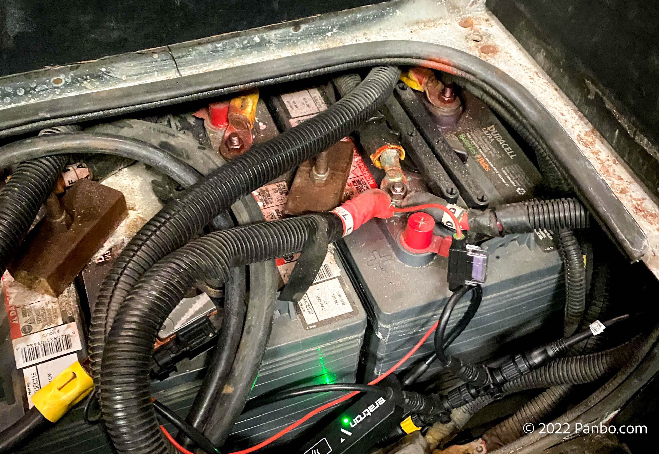
From the factory, Harvey came with four GC2 6-volt golf cart batteries in a two series by two parallel configuration. With each 6-volt battery rated at 230 amp hours this provided a total capacity of 480 amp hours at 12 volts. Because these batteries were flooded lead-acid, I didn’t run them down below 50 percent state-of-charge (SOC), meaning I had 230 amp hours of useable capacity at 12 volts.
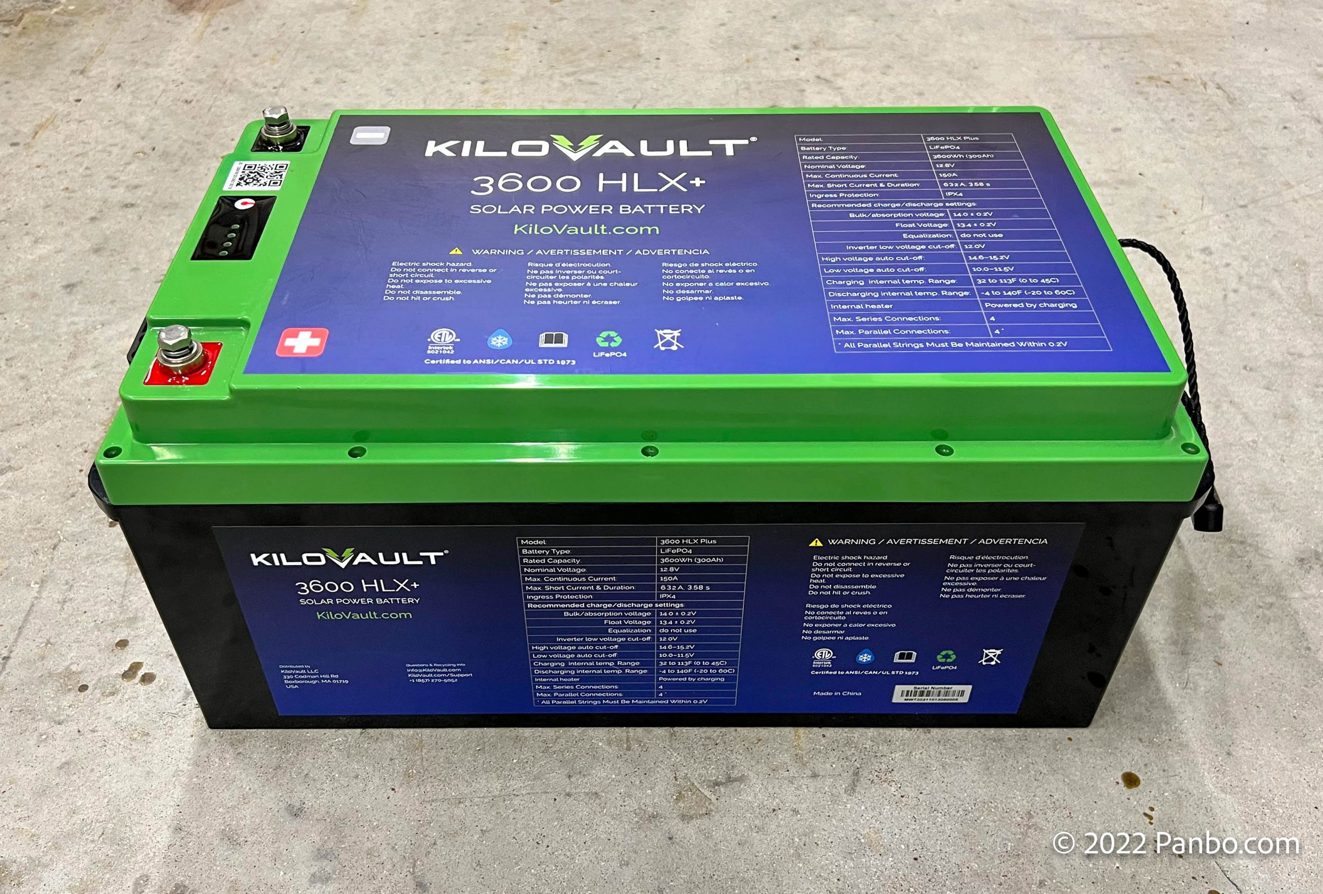
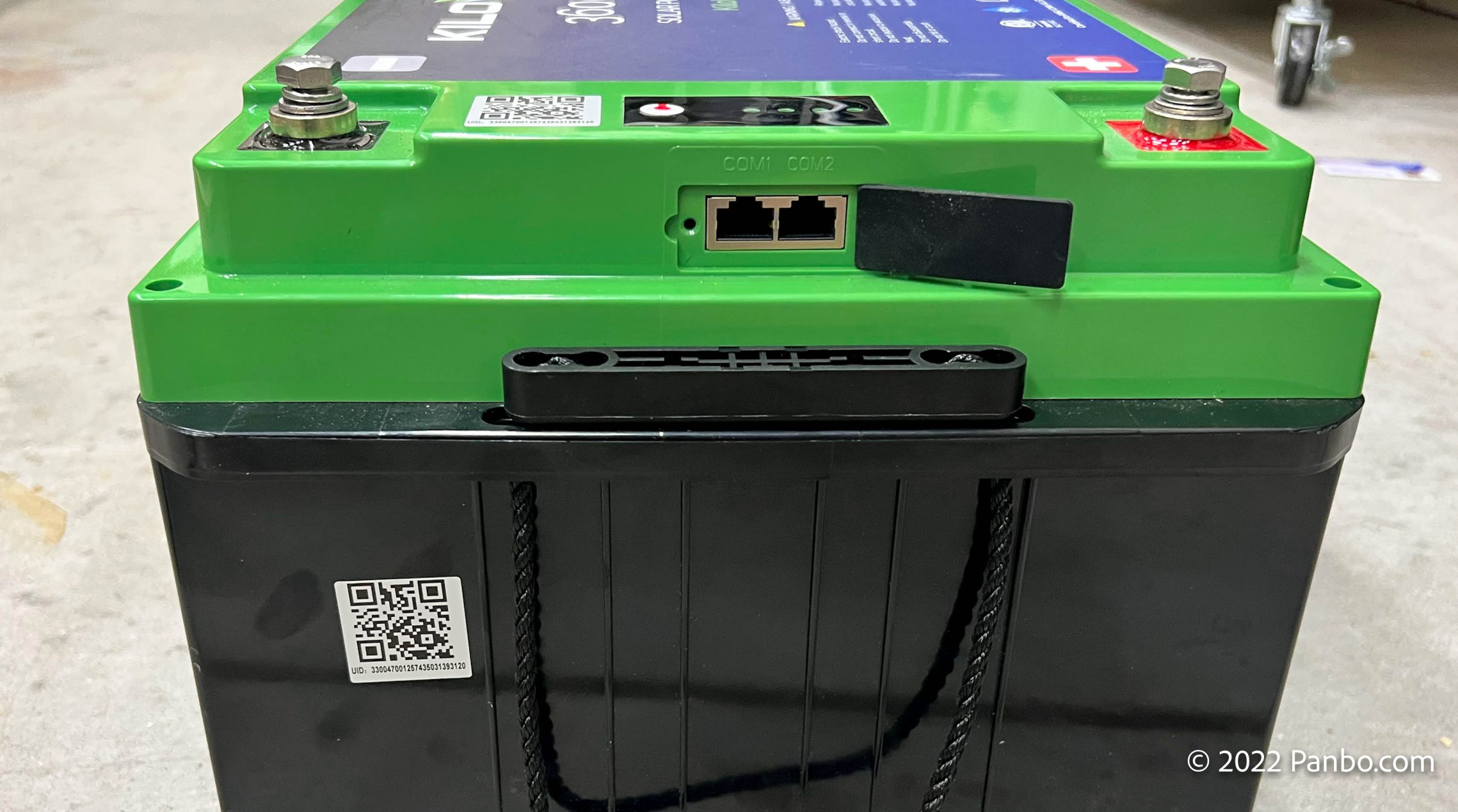
I replaced the four GC2s with two KiloVault 3600 HLX+ LiFePO4 batteries. I’ve previously written up the HLX+ line of batteries and run down their features and impressive build quality. But, just as a reminder, HLX+ batteries are available in 100 amp hour ($699), 200 amp hour ($1,345), and the 300 amp hour ($1,895) size I’m installing. All sizes feature heating, Bluetooth communications, push-button charge level indicators, and communications ports for future enhancements.
These batteries will be installed in parallel for a total of 600 amp hours. Running them down to 20 percent SOC will give me a usable total of 480 amp hours. That’s more than double the capacity of the previous batteries. I’d already made significant changes to the DC system to get it ready for lithium batteries. I outlined those upgrades in my entry from last summer, but to summarize I already replaced the original Magnum inverter that lacked LiFePO4 charge profiles and replaced the relay connection between the chassis and house batteries with an Orion DC-DC converter. Mylast charge source is a Victron SmarSolar 100/50 which is also ready for LiFePO4 charge profiles. So, all my charge sources are easily reprogrammed for LiFePO4 profiles.
Physical install
The factory location for the batteries on Harvey is under the entry stairs, a location I’ve often found inconvenient. Well, as it turns out, one battery wouldn’t fit in the space, let alone two. At 20.5 inches long by 11 inches wide and 9.25 inches tall, two HLX+ batteries are a lot bigger than the four 10.25 x 7.125 x 10.875 inch tall GC2s they replace. On the one hand, I wish the batteries were a little smaller, but on the other hand, I think their size and weight come from their build quality. I had a chance to see that quality in the teardown battery KV provided.
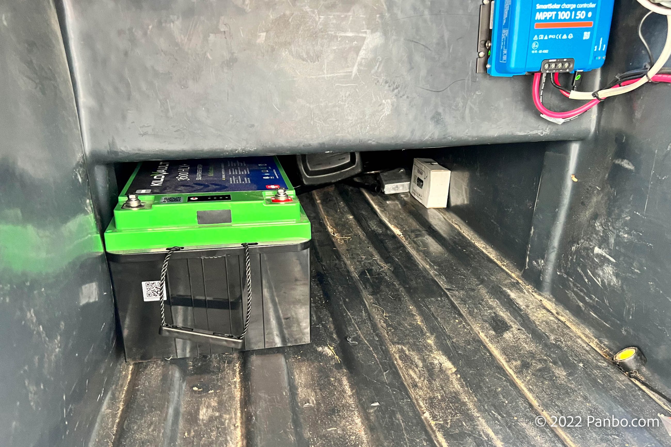
At 88 pounds each I needed to find a location I could mount the batteries that would stand up to the weight of the batteries, offer sufficient vertical clearance and not subject the batteries to potential damage. The location I selected is in one of the under-body storage compartments. The batteries are located under the center of the RV in an area with reduced vertical clearance. There’s just enough room for the batteries and they’re still close to the original spot, so cable routing isn’t too different.
Making the connections
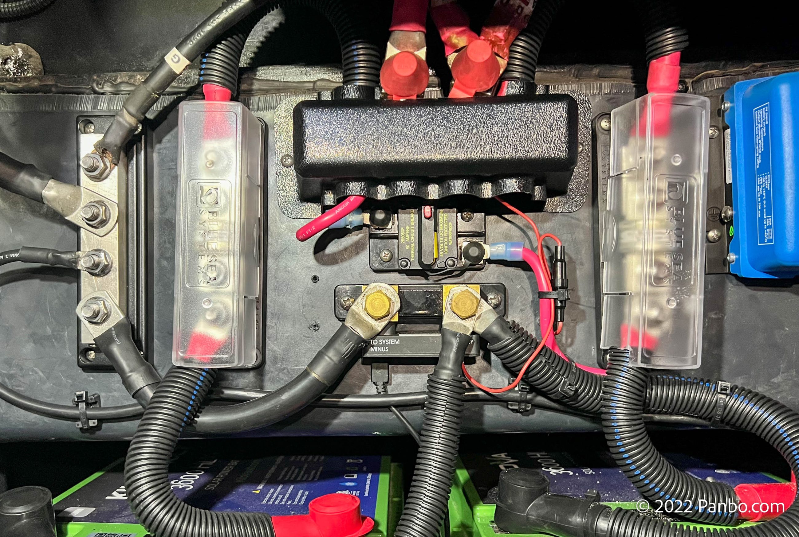
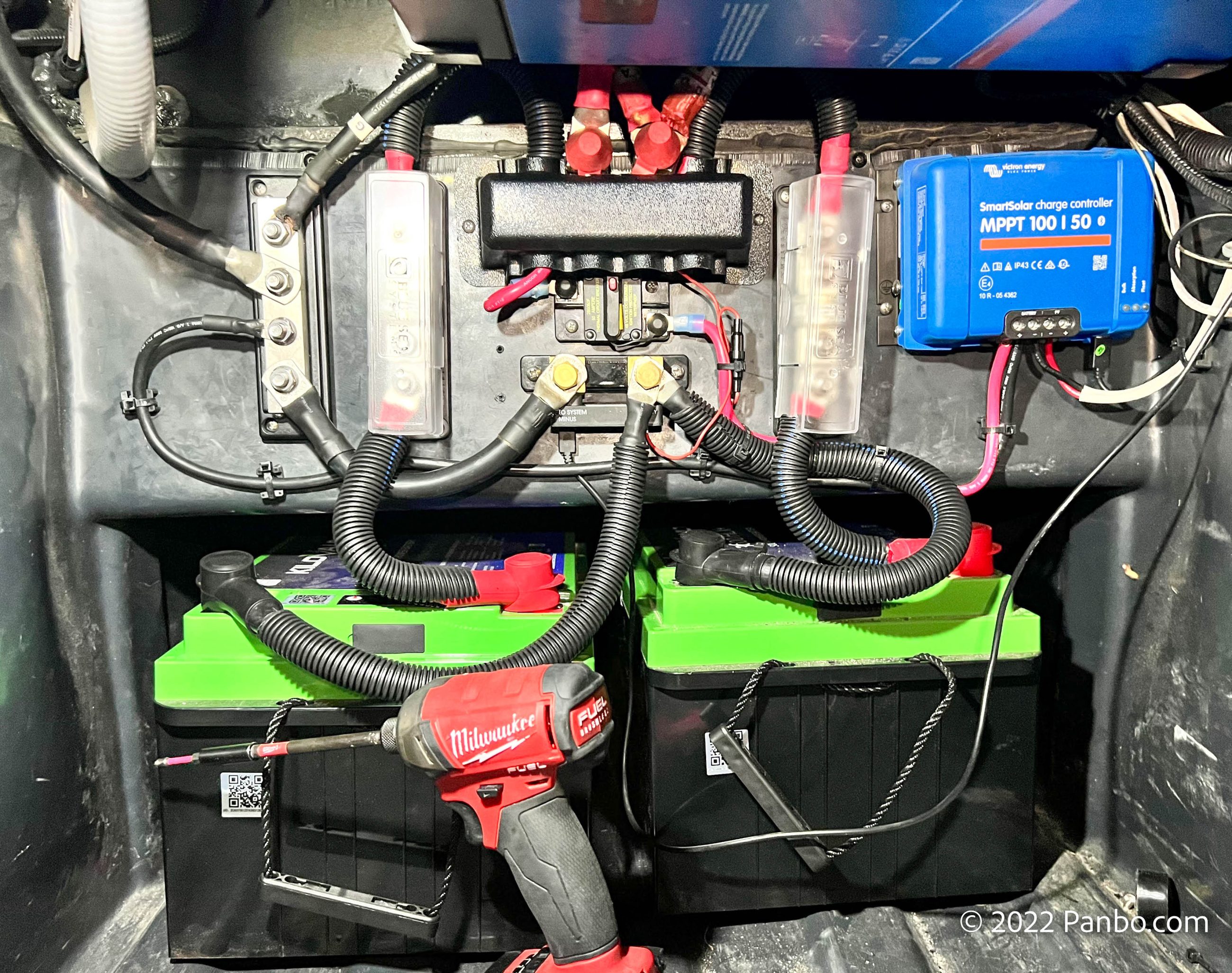
My original plan was to reuse the RV’s existing power distribution. That plan didn’t survive a careful inspection of the wiring. I realized the fuses wouldn’t be adequate for the energy potential of the new battery bank. I couldn’t find specific standards for installing lithium batteries on an RV. So, I decided to follow ABYC’s E-10, E-11, TE-13 (and now E-13). Based on the size of the battery bank ABYC’s standards require the primary battery fuses to have a 20,000 amp interrupt capability (AIC). Class T fuses are the only commonly available option to meet the requirements, so that’s you see in the picture above, with clear covers.
Interestingly, I think this might be the only install I’ve ever done where I’ve been able to get close to placing overcurrent within 7 inches of the battery. In addition to the class T fuses on each battery, I moved the primary fusing for each load to MRBF fuse holders and fuses hung off the positive bus bar. In the photo above, the cover is on the bus bar so you can just see the fuses poking out from under the cover.
Immediately below the positive bus bar, there’s a Blue Sea circuit breaker for the connection to the solar controller. Just below that breaker is the Victron SmartShunt battery monitor.
Putting the batteries to work
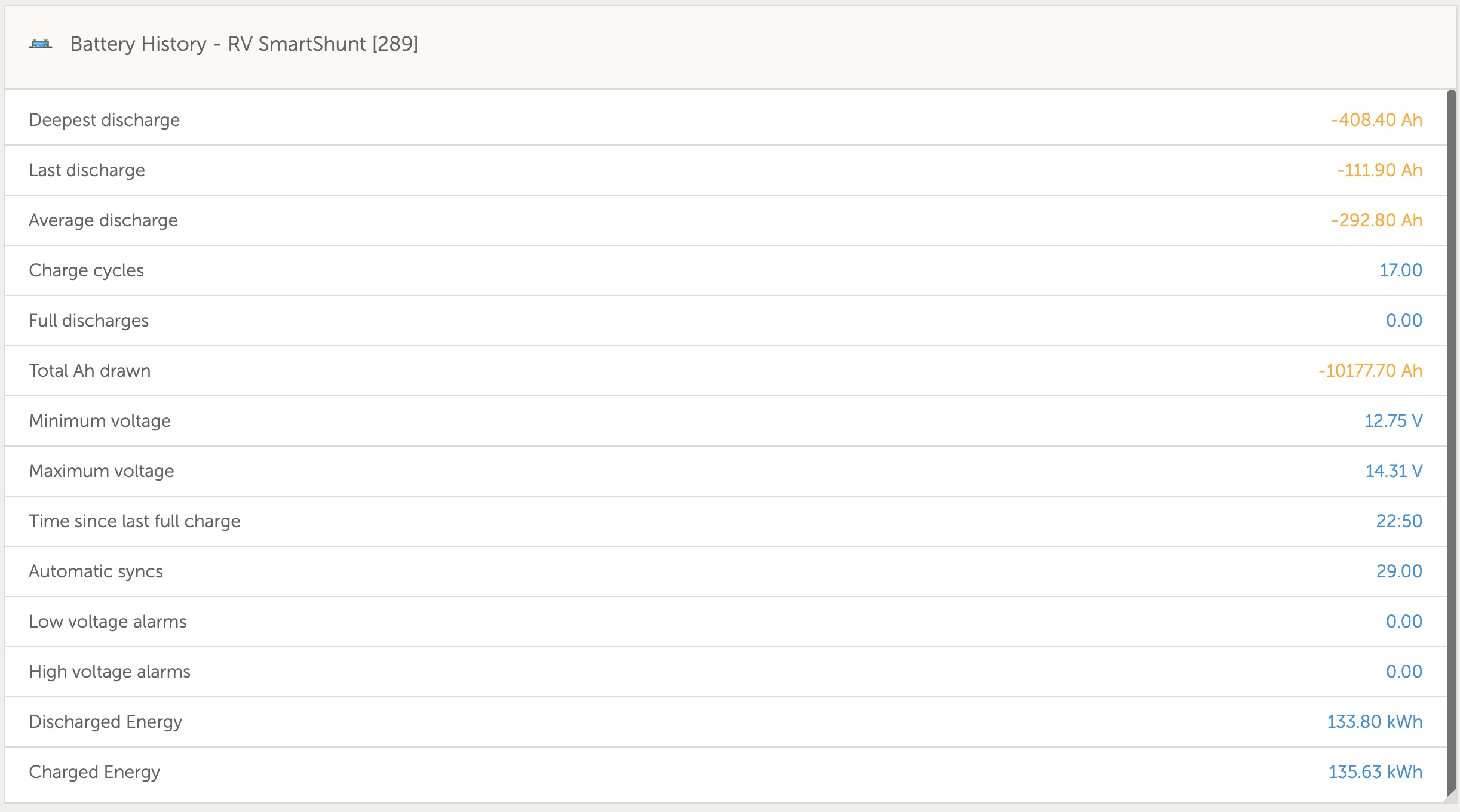
Armed with new and improved batteries, my family and I hit the road. We travelled for a little over six weeks to locations with power availability ranging from 240 volt, 50 amp to absolutely none. In that time we consumed about 10,000 amp hours from the batteries. The lowest voltage the SmartShunt recorded from the batteries was 12.75 volts. As I’ll cover later, that’s despite some pretty massive loads on the batteries.
The screenshots showing the operation of the batteries all come from Victron’s VRM portal. I’m using a Raspberry Pi running Victron’s Venus OS to control the system.
I wish there’s more I could say about their general performance, but sometimes no news (or at least not much news) really is good news. The batteries have done what I hoped they would. When power is needed, they’ve provided it. When power is available to charge them, they accept it. Like every LiFePO4 battery I’ve tested, the batteries accept charging current as fast as it’s provided, right up until about 95-97 percent SOC.
I’ve found that LiFePO4 installations require significant design and planning to be properly and safely installed. But, with a successful design, operations of LiFePO4 batteries seem to fade into the background. The characteristics of the batteries mean they don’t need special care. The batteries go about their business happily and quietly.
Equipped with 700 watts of solar, Harvey can go for days without shore power. On sunny days, the batteries achieve full charge by about 3 pm. Cloudy days often mean dipping into the batteries a little further. With lead acid batteries, that’s something that I monitored carefully to avoid hurting the batteries with excessive partial state of charge (PSOC) cycling. PSOC cycling refers to discharging and charging the batteries without reaching a 100-percent state of charge. Fortunately, LiFePO4 batteries don’t have any trouble with PSOC cycling.
Turning up the load
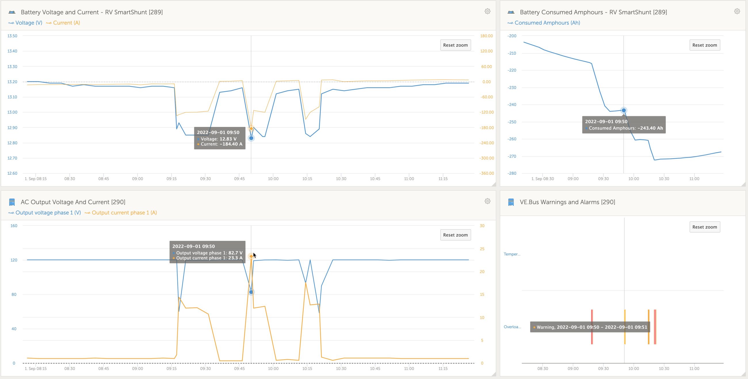
After great success running the DC system of the RV and several AC loads through the inverter, I decided to turn up the load. The single largest loads on the RV are the two rooftop air conditioners. These are 13,500 BTU each and draw about 12 amps of AC power once they’re running. I don’t have soft-start kits on the air conditioners, so their inrush (startup) current demands are quite a bit higher. In fact, I measured inrush at about 24 amps. Those loads are right on the edge of what the 2,000-volt-amp MultiPlus I have can handle. At times, starting up the AC was enough to trip the overload protection on the inverter. But, more often than not, the inverter held up to the inrush load and the AC started and ran perfectly.
As you can see in the top left chart above, starting the inverter drew 184 amps as measured by the SmartShunt. Impressively, even under this sizeable load, the batteries were still pumping out 12.8+ volts. With 700 watts of solar and 480 useable amp hours of battery capacity, I found the load of one air conditioner, a household refrigerator and a few other small loads would deplete the batteries in about 6-7 hours. That time is highly variable depending on outside temperature and how often the air cycles on and off. If I were sizing the system to run the AC on a more permanent basis, I’d probably want more like 14,000 watt hours of capacity, or double my current capacity.
The future: communications, updated mobile app, and E-13
KiloVault has been promising a communications bridge that leverages the communications ports on the batteries for some time. In my recent conversations with KiloVault, I learned they plan to launch the bridge at next week’s Solar Power International show. I’m also pleased to report that KiloVault says they’ll be updating the mobile app at the show as well. As I noted in my previous writeup, it’s the one aspect of the batteries I thought was underdeveloped.
ABYC ratified E-13, a standard for the installation of lithium-ion batteries on boats at the end of July. The standard doesn’t take effect in July of 2023, but I think it’s prudent to start looking at compliance now. From what I can see, the HLX+’s only potential E-13 compliance issues are in the documentation requirements. I certainly don’t expect they will have any troubles updating their documentation by next summer to meet the standard’s compliance date.
Final thoughts
I really don’t have anything negative to say about the HLX+ besides my gripes about the mobile app, and that will hopefully be remedied very soon. I think the price is fair and the performance is strong. However, the testing isn’t over. I’ve consumed 10,000 amp hours of power from the batteries. At 80 percent depth of discharge (DOD), the batteries are rated for 5,000 cycles. With two 300 amp hour batteries that means an 80 percent DOD cycle is 480 amp hours. Multiply that by 5,000 cycles and you realize these batteries should deliver 2.4 million amp hours. So, I’ve used 0.4 percent of their rated life. I’m here to tell you it’s been a very positive 0.4 percent. But, I’ll keep testing and report back if anything changes in the next 99.6 percent.


Thanks Ben, good write-up. Sounds pretty trouble free. Couple of things – You have a typo near the beginning – “this provided a total capacity of 430 amp hours at 12 volts….” I think you meant 460 amp hours.
Also – is there a particular reason you used separate positive/negative cables from each battery to the bus, instead of cabling the two batteries together, positive-positive, negative-negative, and then run single cables from there? Just curious….
Grant, I don’t know Ben’s thoughts, but the usual reason for the arrangement he used is to equalize the resistance for each battery, so both will equally share the loads. Jumpering A to B then from B to the load buss means that A will have slightly higher resistance, and will contribute less to the load. Over time, this can be a serious issue, as the effect is cumulative.
Hartley
S/V Atsa
Thanks Hartley, I’m familiar with the concept, but I thought equal length jumpers in this configuration would nullify that. Perhaps not.
Grant,
First, you’re right, that’s a typo, though I think at 80 percent of 600 it should be 480 amp hours. I’ll go fix that.
With two batteries and short runs I think the way I did it is equally efficient to battery interconnect links and then coming off the positive of one battery and the negative of the other. Either way, I needed four cables. I was careful to keep cable lengths identical between the batteries and so far I’m seeing pretty equal rates of discharge. I believe it’s basically method 3 in the SmartGauge article on cabling banks (http://www.smartgauge.co.uk/batt_con.html).
My understanding is that what you’re trying to accomplish is equal length cabling to each battery. As long as you can get that done, you’re in good shape.
-Ben S.
I installed five Kilovault 300AH batteries a year ago on my sailing cat. Couldn’t be happier with them. As Kilovault requires, I used equal length cables as you did. After a year of use the app shows each battery as still having more than the rated amp hours and the internal cells are so well balanced that they are within .01 volts of each other. So they are charging and discharging in perfect sync. I think equal length cables may be the key to lithium battery long life. If you are installing more than two batteries in parallel the old LA method of a positive cable at one end of the bank and negative at the other end causes LFPs to charge and discharge unequally due to their low internal resistance. Or so I’m told.
Thanks Ben. I’m sure it’s fine – I was just thinking you could have saved a little cable and also eliminated one of those Class T fuses/holders, which aren’t exactly cheap…
The Smartgauge link is great information, which I’d seen before – I do note, however, their statement near the end, “Finally, if you only have 2 batteries, then simply linking them together and taking the main feeds from diagonally opposite corners cannot be improved upon. ”
Cheers,
Thanks for this excellent writeup Ben.
My 660A/h Firefly Housebank is 5 years old and still works pretty well but the voltage drop to ~ 12.0V as it approaches 50% SOC and the slower charging acceptance as it rises above 75% SOC has me lusting after a LiPO4 house bank. We spend a lot of time away from the dock and would really appreciate reducing our generator time; especially in the winter. I can quite easily muster ~ 240A of ’12V’ charging with the engine and generator running (even more on a sunny day and the solar panels working) but this quickly tapers off to half that after an hour of charging despite there still being a 200 A/h deficit to make up.
I wonder if you could comment on how one would use these Kilovault batteries as the house bank on a vessel that also has AGM Lead acid batterie: think AGM’s or Carbon Foam for the bow and stern thrusters as well as an AGM start battery?
Would it be acceptable to run the alternator and AC chargers through a battery isolator to prevent the mixed battery issues that one is supposed to avoid with LiPO4? I would assume that having the Lead Acid batteries in the system would also prevent an alternator meltdown if the BMS of the LiPO4 house bank went off-line suddenly?
Thanks for your insights or thoughts on this.
-Evan
Evan,
First, by getting 5 years out of a Firefly carbon foam bank, you’ve done better than many boaters I know. Second, it sounds like your bank is now delivering a lot less than its rated 660 amp hours. I’d hazard a guess that you’re closer to 425-475 amp hours. So, in reality, when you’re seeing 12.0 volts and 50% state of charge, I’d guess you’re a meaningful amount below 50% SOC.
Charge acceptance was the largest factor that pushed me towards LiFePO4. Having your batteries eat all the charge you throw at them is a luxury measured in peaceful time without the generator running.
A boat with mixed chemistries is often best served by DC to DC converters to deliver charge current in the manner appropriate to each chemistry. To make concrete recommendations, I’d need more information. Particularly about your alternator regulation scheme, solar capacity, and generator or shore power based charge sources.
A battery isolator isn’t sufficient to deal with multiple chemistries. Your batteries would be combined during charging and you wouldn’t be delivering the appropriate charge voltages for your varied chemistries. Additionally, combining the batteries during charge cycles would run afoul of ABYC and other standard’s bodies prohibition on mixed chemistry banks.
-Ben S.
Thank you Ben.
This is helpful in steering my research going forward.
I probably shouldn’t burden you or your readers with too much information but perhaps other readers could find it an instructive case study?
I have a Nordic Tug 37, we use all year round with occasional usage at or below freezing temperatures. (The engine room is only very rarely below freezing.) In winter, at anchor, with the heater going, & no solar, we can sometimes be down as low as ~350 Ah for the day.
For charging away from the dock, we have a Cummins 5.9 diesel driving a 120A alternator with a Balmar external regulator and an Onan 9.5 KW generator + 2x 275 W panels (550W) of Solar on the pilothouse roof running through a Morningstar MPPT controller.
The 120A alternator feeds the various battery banks (Start, House, Thrusters through a battery isolator (Victron Argofet 3 /200A). A Magnum 2812 inverter charger represents our main charger with an auxiliary 40 Amp Xantrex charger connected to the start battery (Lifeline 8D AGM) This charger can also help charge the main House Bank via a relay.
The Forward thruster & windlass run off a bow 8D AGM & the aft thruster has another AGM battery bank tied into the house Bank via 4/0 cable.
I monitor the house bank SOC via a Victron 701 Shunt monitor & probably obsess way too much over the SOC.
I recently switched my charging profile to a CC/CV scheme for the house bank as Fireflies prefer no float but can keep the start battery isolated with the Auxiliary Charger on an AGM friendly float regimen.
Leaving an anchorage with a big battery deficit, with the generator & engine on, we can produce ~ 250A of charging but the batteries will very quickly (within 30-60 minutes) choke that back to half of that or less.
I’ve resisted going to LiPO4 so far because I couldn’t see how to safely & elegantly combine these differing chemistries but would really welcome the increased charge acceptance and more consistent voltage that a LiPO4 house bank would offer. If I could solve that problem, I would probably jump at a couple of these KiloVault 300 A/h batteries.
Forgive me if this is too much information.
I will have research the utility of DC – DC converters.
-evan
Evan,
I think this is a good and instructive case for how to design a LiFePO4 friendly DC system. When looking at how best to tackle the design of a system with multiple chemistries, the first decision to make is which bank will connect directly to the alternator.
In your case, especially given that you’ve got an externally regulated alternator, I would lean towards running charge directly a hypothetical new LiFePO4 house bank. In turn, I would use a DC-DC converter to redirect some of that charge to your engine, bow thruster, and stern thruster banks. If I’ve got this right, all three of those banks are AGM and hence you could use a single (or multiple ganged together) DC-DC connected to an ACR or battery combiner to charge those banks from the alternator. Although all three of those banks are high load, they also typically experience very short load durations so their charging needs really aren’t that great.
The same DC-DC charger can take charge from the inverter and redirect it to the engine and thrusters batteries. Additionally, I think the Victron BlueSmart chargers (https://www.victronenergy.com/chargers/blue-smart-ip65-charger) are small enough and cheap enough that, in light of the physically disparate location of the three batteries, you could run an individual charger to each battery.
In short, I think your boat is pretty well setup for LiFePO4 and you’d be looking at manageable changes to make it all work together.
-Ben S.
FWIW, I agree with you, Ben 🙂 One comment – I note that Evan is operating year-round, so bitter cold mornings are a distinct possibility. LiFePO4 batteries do not want to be charged cold, and my Victron BMS cuts off charging at 5 degrees C (41 F) . This caused a problem on our sailboat, which is on the hard without shore power in Maryland this winter. I constructed a heater using resistors and an aluminum plate (provides approximately 45 watts of heat in full sun) regulated by a cheap digital thermostat. I also added a significant amount of insulation around the battery (about 3″ of batting all around).
Even though the local WX has been down to 0 C a couple times since, the battery has stayed warm overnight and heats up to maybe 11-12 C after an hour or two of daylight on the solar panels. I ran the heater off of the raw solar panels so it wouldn’t run the battery down if it got REAL cold 🙂
Obviously, the heater gets turned off and the insulation removed in the spring!
Hartley
S/V Atsa
Thanks Ben,
This is hugely helpful.
If I understand it correctly, the DC-DC converters would be there to provide isolation between the various battery banks and prevent reverse flow of current. Is a Mosfet (eg Argofet) battery isolator not providing the same function? From my reading at https://marinehowto.com/drop-in-lifepo4-be-an-educated-consumer, it looks like the battery isolator would allow higher charging currents than using DC-DC converters… Clearly, I have more reading to do to understand this properly.
As I mentioned, I presently have a 40A charger that can be isolated from the House Bank allowing it to be configured in a more appropriate AGM charging profile for the start and thruster batteries but, I’m think that when away from the dock and on the hook, it would make sense to have the primary Magnum charger and solar charger setup with LiPO4 friendly profiles. The AGM’s might suffer from some days or weeks in a partial SOC but would be restored to 100% SOC upon return to the dock or periodically with some deliberate isolated charging with Float?
Your suggestion of using smaller AC chargers has some merit and will consider that.
Thank you very much for considering these questions.
Much appreciated.
-Evan
Evan,
The core function of a DC-DC converter in this application is to provide appropriate charging voltages to heterogenous battery chemistries. The DC-DC will run a 3 stage charge cycle like any other battery charger, the only difference is that instead of an AC power source, it’s using power from another DC source. That means you can properly Bulk, absorb, and float charge AGMs with power coming into the LiFePO4 bank conditioned for their charging needs.
I struggle to think your AGMs would really be experiencing PSOC conditions very often. At anchor, you’re not likely to have much thruster runtime. So, the main thing you might be concerned about would be current depleted by the windlass. A rather large windlass like a Maxwell 3500 is rated at 100 amps at 12 volts. Imagine you run your windlass for five minutes (and that’s a lot of windlass run time). In 5 five minutes at 100 amps, the load would consume 8.33 amp hours. From an AGM, peukert’s algorithm suggests you might be closer to 10 or 11 amp hours from the battery, but that’s still a small amount of current for a 30 amp DC-DC charger to replace. The problem isn’t likely to be the DC-DC’s ability to produce charge current, it’s more likely to be the AGM battery’s ability to accept charge when it’s close to 100% SOC.
-Ben S.
The above is how I’ve tackled mine.Could the OP could simply run a fused reasonable size wire (maybe 6 gauge) between the three AGM batteries to keep them charged equally? But I have a related question – can the Victron DC/DC charger absorb the surge from the alternator if the lithium BMS shuts off by directing the surge into the start battery? I believe it would but can’t find that written down anywhere. I also have a Balmar alternator protector but would like to not depend only on that.
Carl, an alternator generates a surge when its disconnected (though there are good devices to reduce it). The DC-DC charger should provide some load (even if the batteries its charging are “full”) so a major surge shouldn’t happen.
I’d still install a surge arrestor device at the output of the alternator JIC.
The best way to charge multiple AGM batteries from a single charger would be to implement battery combiners (AKA voltage-sensitive switches) to combine them when the charger starts up. You could use diodes, but that introduces some other issues with voltage drop, etc.
Hartley
S/V Atsa
Reply to Ben re: DC- DC converter.
Thank you for clarifying this point. That makes more sense now.
If I understand your suggested configuration, I could have a direct charging route to my LiPO4 bank from the primary AC chargers, the alternator and Solar with all of these chargers terminating on a common bus-bar to feed the LiPO4 bank. They should all be programmed to use similar LiPO4 friendly charge profiles. This would maximize the potential charging current to the House Bank. (i.e. They would not pass their charges through the DC-DC converter to feed the House Bank.)
The lead acid start battery and AGM thruster banks would receive their DC power from these same charging sources (feed from final common bus-bar via a DC-DC converter programmed with an AGM profile. (The current would be passed through a Mosfet Battery isolator to distribute the charge and maintain isolation for all 3 of these AGM banks.)
I’m thinking that it would probably still be worthwhile investing in an alternator protection module to protect the alternator should the BMS go offline.
Unless I’m missing an important detail, it looks to me that these Kilovolt HLX+ batteries could be integrated safely and relatively simply into this mixed system after all.
Thank you very much Ben for your patience and help in working through these details.
PS: Here on the West Coast, (Victoria, BC) we rarely see temperatures below freezing and even then to only a moderate degree. It’s very rare to get below freezing in the engine room and should that happen, I note that the Kilovolt batteries have a heater function that comes on with the AC charger to bring the batteries up to a functional temperature and to allow charging at low ambient temperatures.
Edit to my comment above:
The lead acid start battery and AGM thruster banks would receive their DC power from these same charging sources. They would get their power feed from the LiPO4 final common bus-bar and this power would pass through a DC-DC converter programmed with an AGM profile.
A couple of lessons learned from my installation. I’ve had five 300AH Kilovaults for the last 18 months. It’s a cat so two lead acid start batteries each charged by a DC-DC charger. 1) I replaced the OEM 120amp internally regulated alternators with Balmar XT170s that fit in the same space. These stand up to the load of lithium much better providing 150 amps even when hot (the 120’s put out about 60 amps when hot). 2) I tried using a Balmar 618 regulator first but it didn’t give more than 80 amps. I’ve used Balmars in the past without trouble but something about this setup didn’t go as well — so I switched to a Wakespeed regulator which has been great. It can be programmed by Bluetooth from a phone app and also connects to my Victron VRM. 3) I used the Balmar Alternator protector. 4) The Kilovault instructions require that parallel batteries be connected with equal length cables. This insures that they charge and discharge at the same rate as the cable resistance is the same. I ran 2/0 cables from each battery to a new bus bar and then a 4/0 cable from that bus bar to the boat bus bar. There’s a Class T fuse at the 4/0 cable and 300amp MRBF fuses at each battery to meet the ABYC 7” rule . 5) My electrician recommended that I set the solar controllers to the Kilovault spec 14.1v absorption rate but set all other chargers to 13.9v or 14.0v This gets the bank to about 95% and the solar MPPT can then take it to 100%. 6) If you have Victron multi chargers, the absorption time can not be set less than an hour – too long for Kilovault’s spec – their technical support said that an hour is OK if the absorption voltage is 14.0v.
Thank you for these details Carl.
This is very helpful.
Are you happy with the Kilovolt performance?
I hope you don’t mind Ben; but, taking a few pointer from this discussion, I’ve created a draft schematic of what a mixed battery bank configuration using these drop-in Kilovault batteries might look like and posted it here:
https://eheffa.zenfolio.com/img/s/v-10/p1424814975.jpg
It seems to me that if a BMS disconnect were to occur, this system could be protected from an alternator meltdown but I also want a way to prevent loss of power to the DC panel. (Losing the alternator is one thing but suddenly also losing all instrumentation etc. would be extremely undesirable and potentially dangerous.).
I’ve suggested adding an isolated power supply feed from the Start Battery to the DC panel as a backup to the DC supply from the House battery. I’ve notated this as both supplies being isolated from each other by Mosfet isolators but a better solution might be to have an instantaneous switch that turns on the start battery supply to the panel in the event of the house battery going off-line in the event of BMS shutdown. This would only be a temporary supply to the panel until the house bank comes back on line. Would this work? (My current setup uses an ACR relay switch to take the house battery out of connection with the house battery bank when the house voltage drops below a certain threshold to protect the Start battery from inadvertent discharge.)
Another alternative would be to have a smaller LiPO4 battery with its own BMS in parallel with the bigger House Bank batteries that could act as a backup should the Primary BMS go off-line.
Any suggestions or comments appreciated.
Thanks for sharing a schematic!
I have 4 of these batteries (4 x 100Ah) charging by Wakespeed, Victron solar MPPT and Multiplus shore charger when on dock. Question for others with these: do you think it’s worth using the Wakespeed’s “force to float” function (wiring in a switch) and then manually toggling that switch when I know the batteries are at or near 100% and we’re starting our engine?
Since the Wakespeed has a current shunt and Kilovault’s parameters shut down charging quite quickly (2 minutes at 14.1 or 8a tail current for a 4-battery parallel bank), I’m not sure it’s really harmful to bump up to 14.1 for that brief time when we start our engine? Force to float switch is nice but it’d be extra work to wire and remember to flip on / off. Thoughts on whether it’s really necessary?
Is it true that Kilovault has gone out of business – leaving customers with no warranty?
It does appear so. I have a couple of them myself. When Alt e went, so went Kilovault. There is comment that the warranty may be honored by the fabricator of the batteries. And supposedly someone has bought Alt e’s remaining stock and presumably planning a reopening.
Based in part on your review I purchased 8 Kilovault 3600 in 2022 as a house bank for our 50 foot liveaboard trawler. It is stored indoors in Fairhaven,Ma. I can not communicate with the batteries as the app no longer connects. Do you have any insight in how I can go forward managing the batteries? They have been great, allowing us to live on the hook for 1-2 months at a time.