

Maximizing solar production with Victron GX
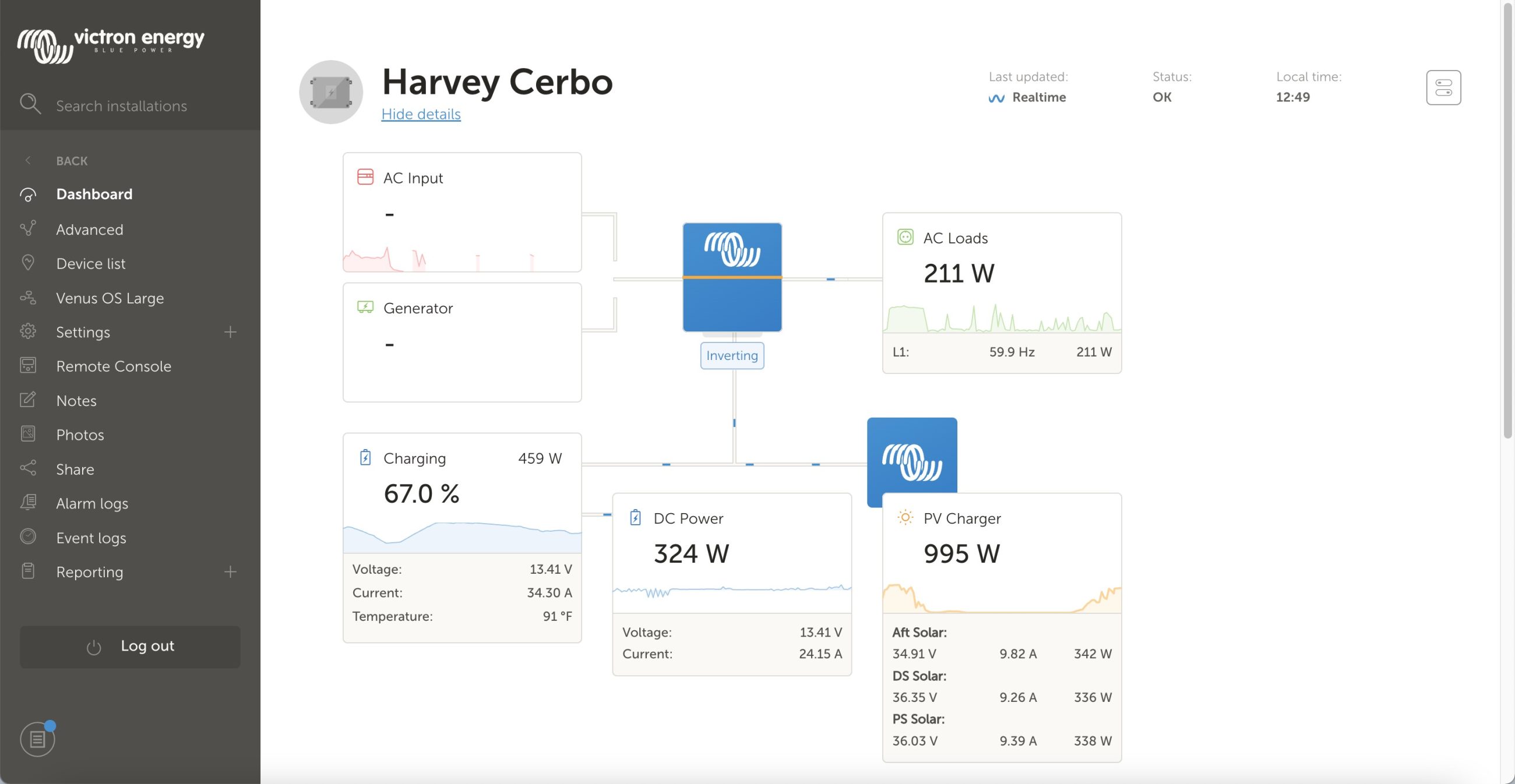
After the loss of Have Another Day, my primary DC test platform is Harvey, my family’s RV. Over the winter we upgraded from our previous 35-foot coach to a 43-foot Newmar Dutch Star. With that upgrade, I’ve added 1,350 watts of solar to the new RV. With all that solar, I wanted to ensure I was taking full advantage of the potential production. That sent me diving through the settings in my Victron system to figure out the best way to manage my system. Currently, I’m using a Virtual Switch in the inverter to manage DC power sources and it’s working quite well.
System overview
Harvey’s DC system is, thus far, a Victron affair. From the factory, Newmar equipped this coach with a Magnum system that I’ve removed. As a data junky, I love the information Victron’s remote access portal, VRM, gives as well as the detailed control of the system’s operations.
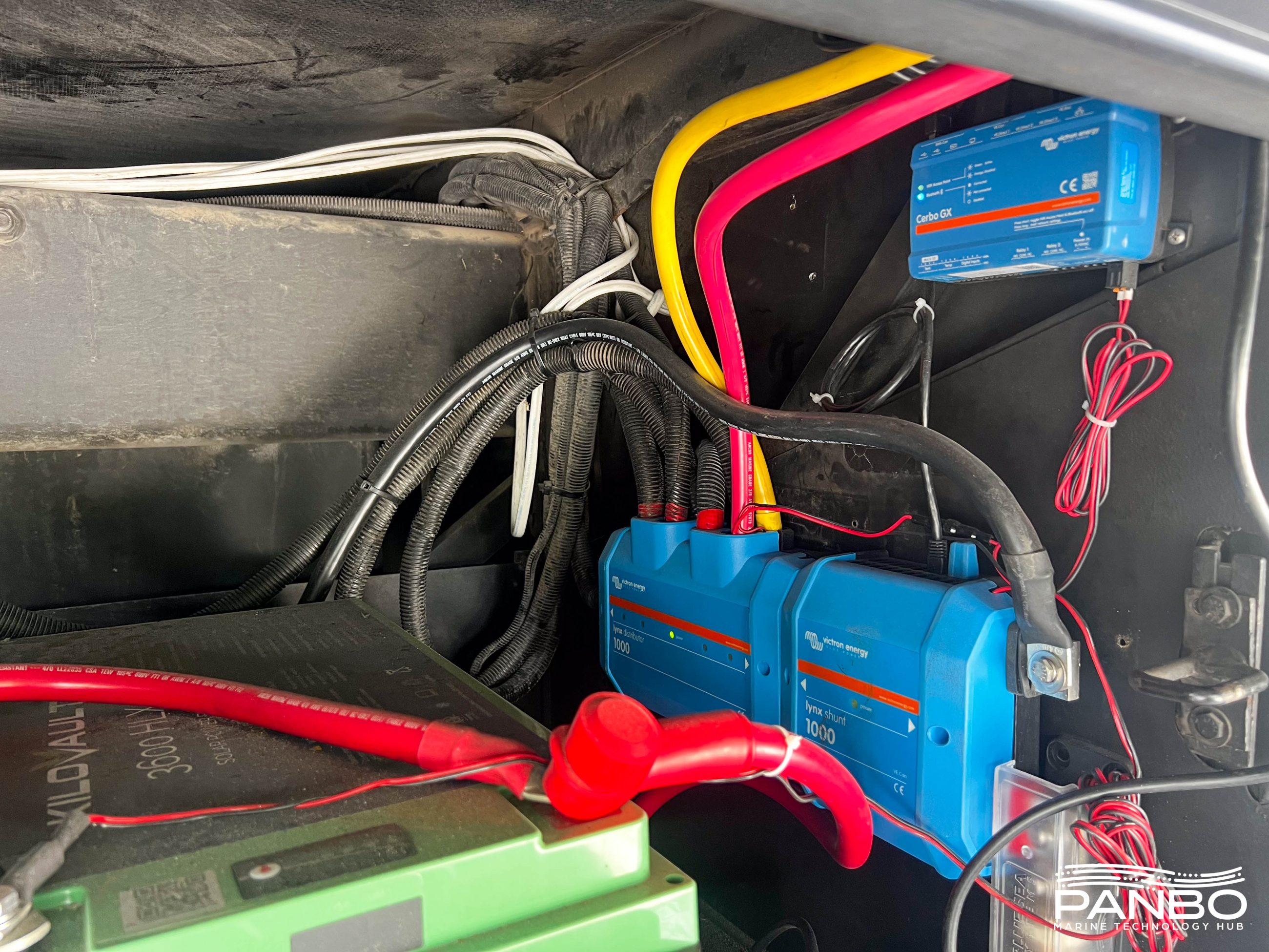
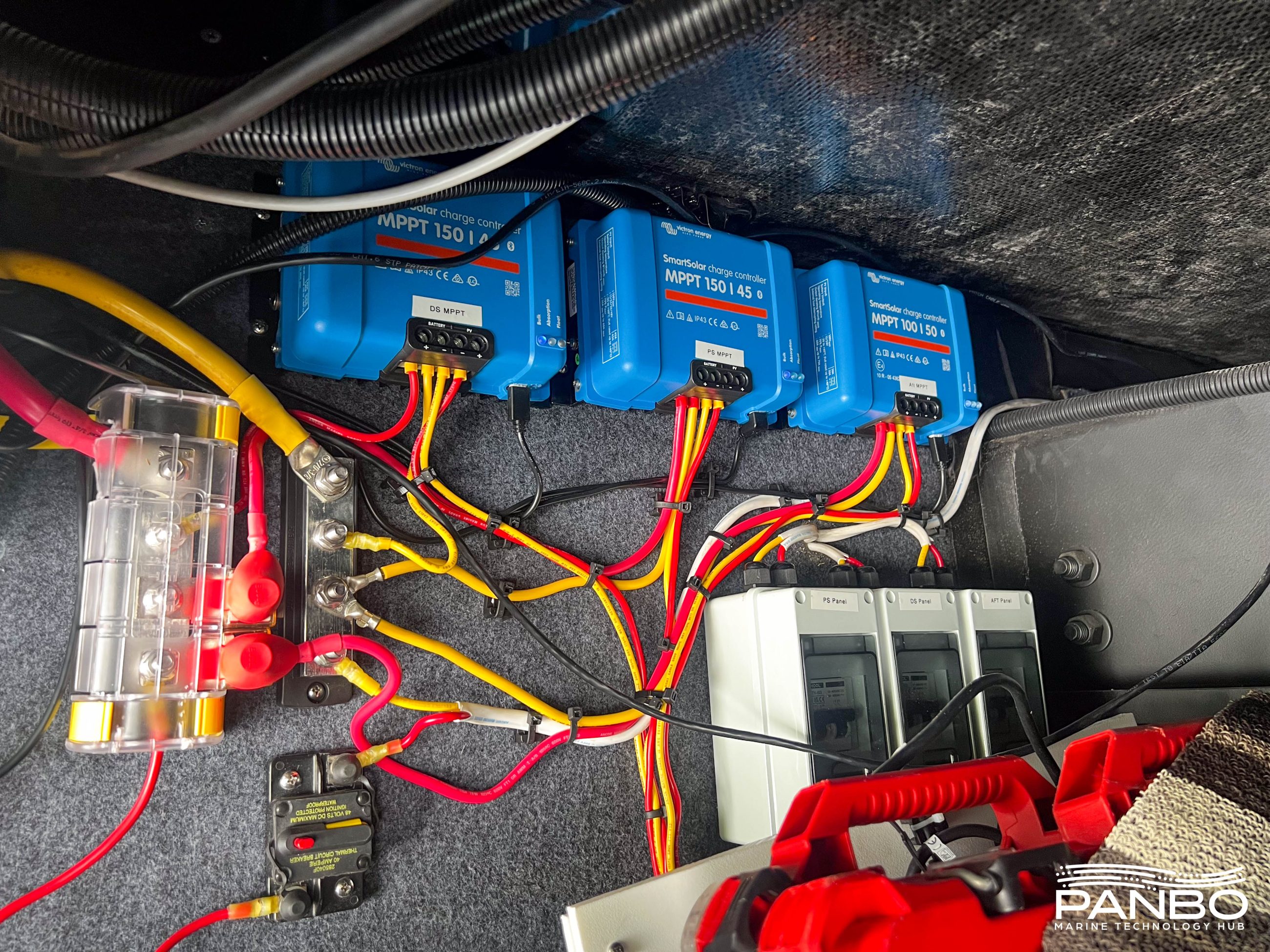
I continue to use two KiloVault HLX+ 3600 batteries giving me a total of 600 amp-hours of 12-volt nominal DC power. These batteries are powering the RV’s house DC loads and a Victron MultiPlus II 3000VA inverter. Charge sources to the system include three 450-watt solar panels connected to three Victron SmartSolar Charger MPPT 150/45 solar controllers. I’m also using a Lynx Distributor and Lynx Shunt for power distribution and monitoring. A Cerbo GX monitors the Victron components via Ve.Direct, Ve.CAN, and Ve.Bus.
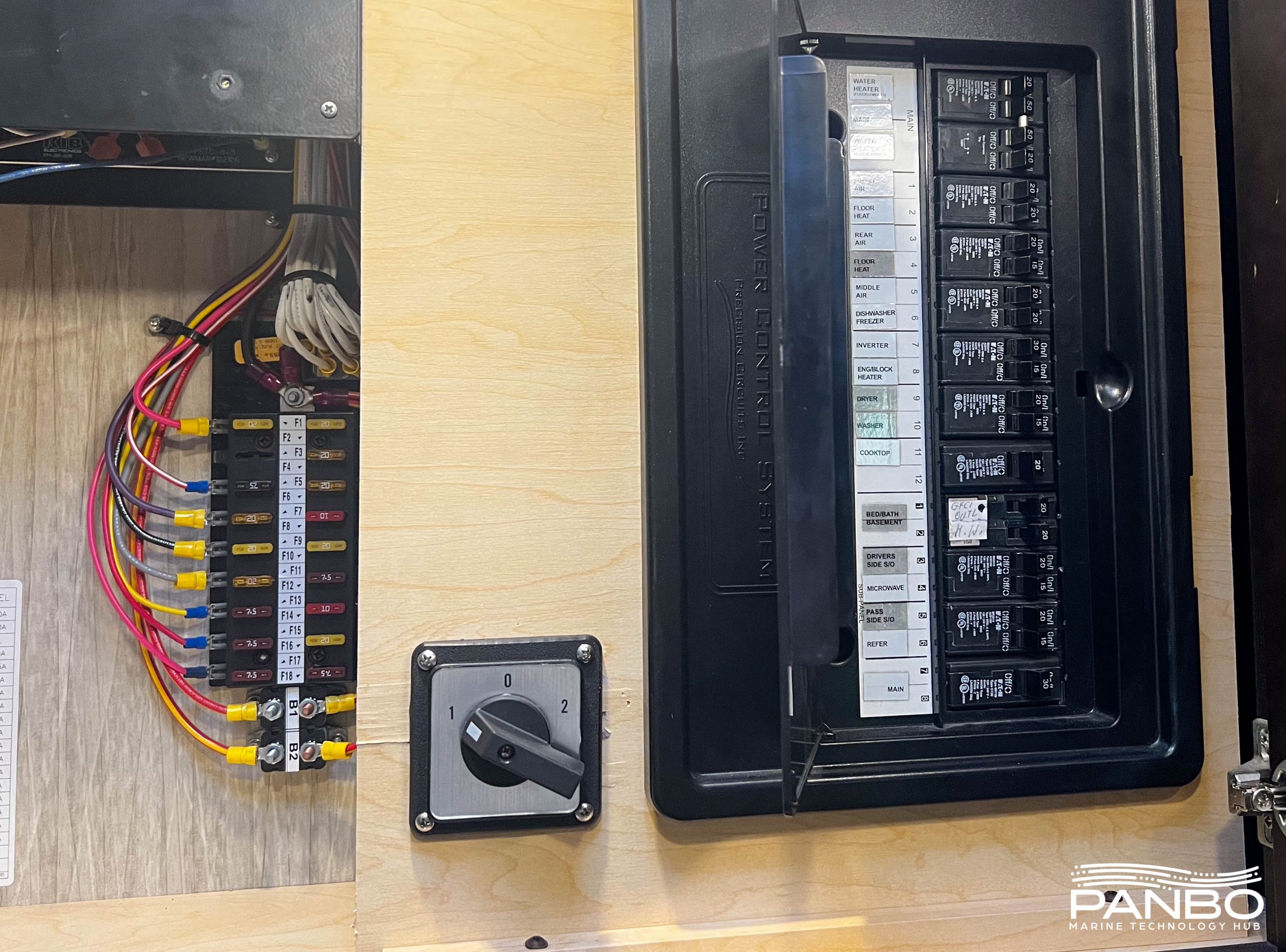
Lastly, I’ve made one important modification to the AC power system of the RV. My coach is equipped with three, 15,000 BTU 120-volt AC rooftop air conditioners. I’ve rewired the middle air conditioner to connect a rotary transfer switch that allows me to power that unit either from the non-inverted or the inverted power bus. That allows me to power that air conditioner without the generator running. But, at 15 amps of 120-volt AC, it’s a big load so either I have limited runtime or I need lots of sunlight to help offset it.
The “problem”
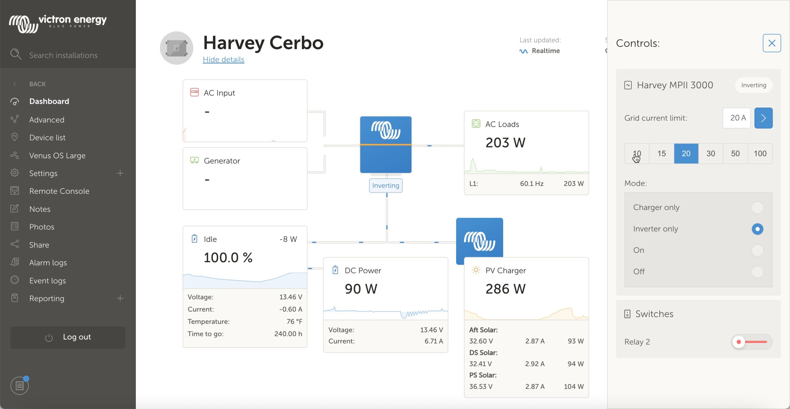
I’m not sure that describing my challenge as a problem is accurate. I guess it’s more of a desire to take full advantage of what I have. It doesn’t make sense to me to use utility power to charge the batteries and run the RV’s loads when I have 1.3 kilowatts of solar on the roof. So, the question is, how do I control shore power-based charging to work for my situation?
For quite some time I’ve manually done this by using VRM to change the inverter mode between on (inverter and charger enabled) and inverter only. When in inverter only, the MultiPlus won’t use mains power to pass through to loads or to charge the batteries. But, wouldn’t it be better if I could leverage all the smarts of my system to not use mains power until the batteries get low? Surely I’m not the first person to want this type of functionality, right?
The solution
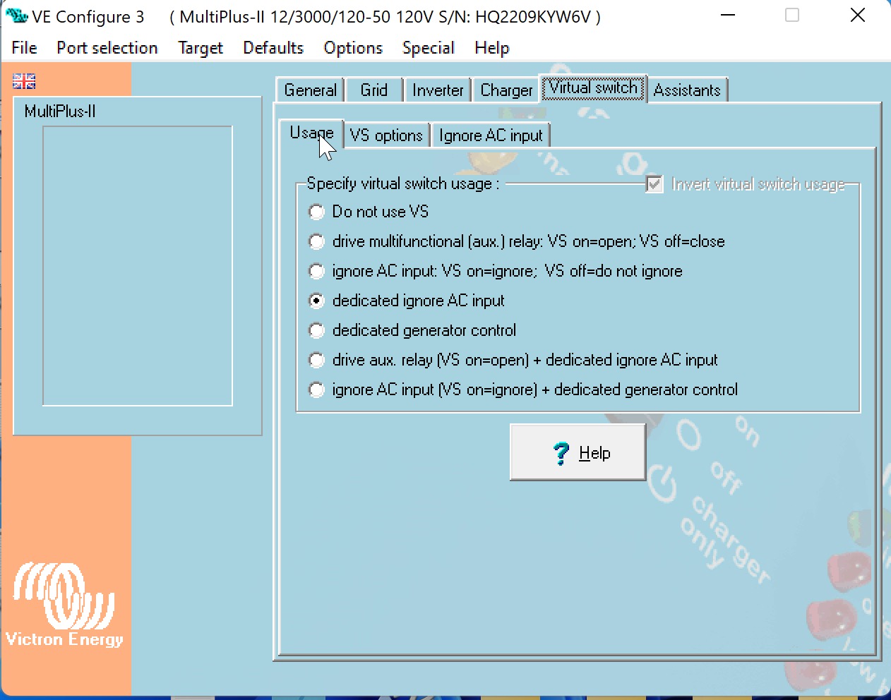
Indeed, I must not be. Victron has implemented a pretty elegant, though I don’t think widely known solution. In fact, in my searches, I found mentions of ignoring AC input dating back seven years. But with a name like “dedicated ignore AC input” I’d say the feature might have a marketing challenge. To effect this change, you will either need a GX device (Cerbo, Venus, Color Control, Raspberry Pi, or the new Ekrano) or an MK3 USB adapter.
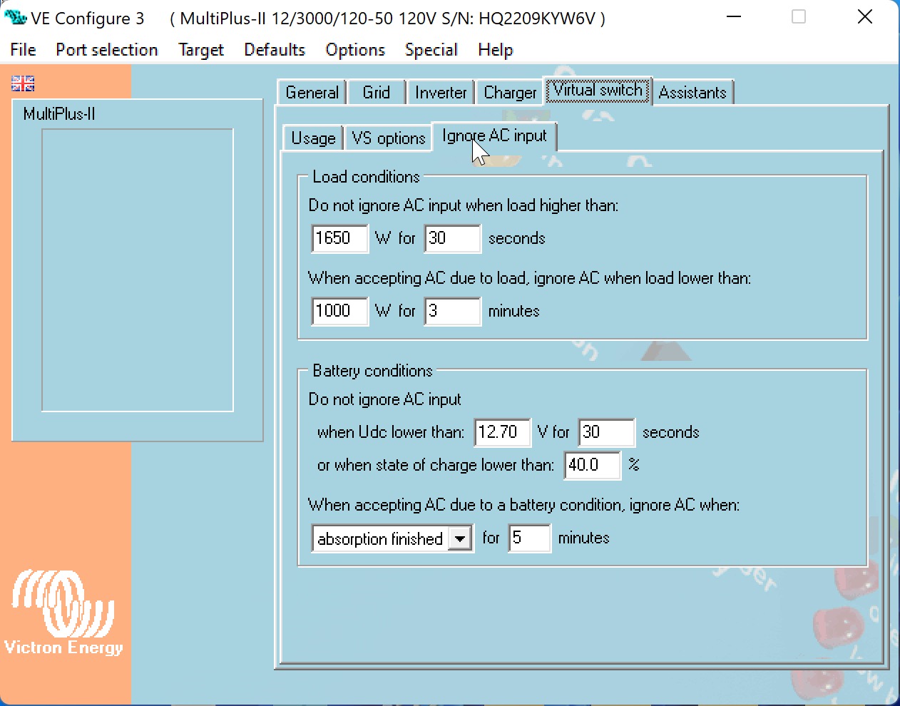
Ignore AC input configures the inverter to ignore its AC input as long as certain conditions are met. These conditions fall into two basic categories, AC load on the inverter and the battery’s state of charge and voltage. In the screenshot above, you can see the configuration I’ve been using. I have configured the MultiPlus II to not use AC power unless there is a load of greater than 1,650 watts for more than 30 seconds. It will continue to use mains power until the load is below 1,000 watts for 3 or more minutes.
Additionally, if the battery voltage drops below 12.7 volts and stays there for 30 seconds or if the state of charge is below 40 percent, the inverter will begin using mains power again. If a battery condition triggers the use of AC power, the inverter will continue to accept power until the specified condition is met. In my case, I’ve configured it to complete the absorption phase of charging and then wait five minutes. That should represent a full charge cycle.
Even more control
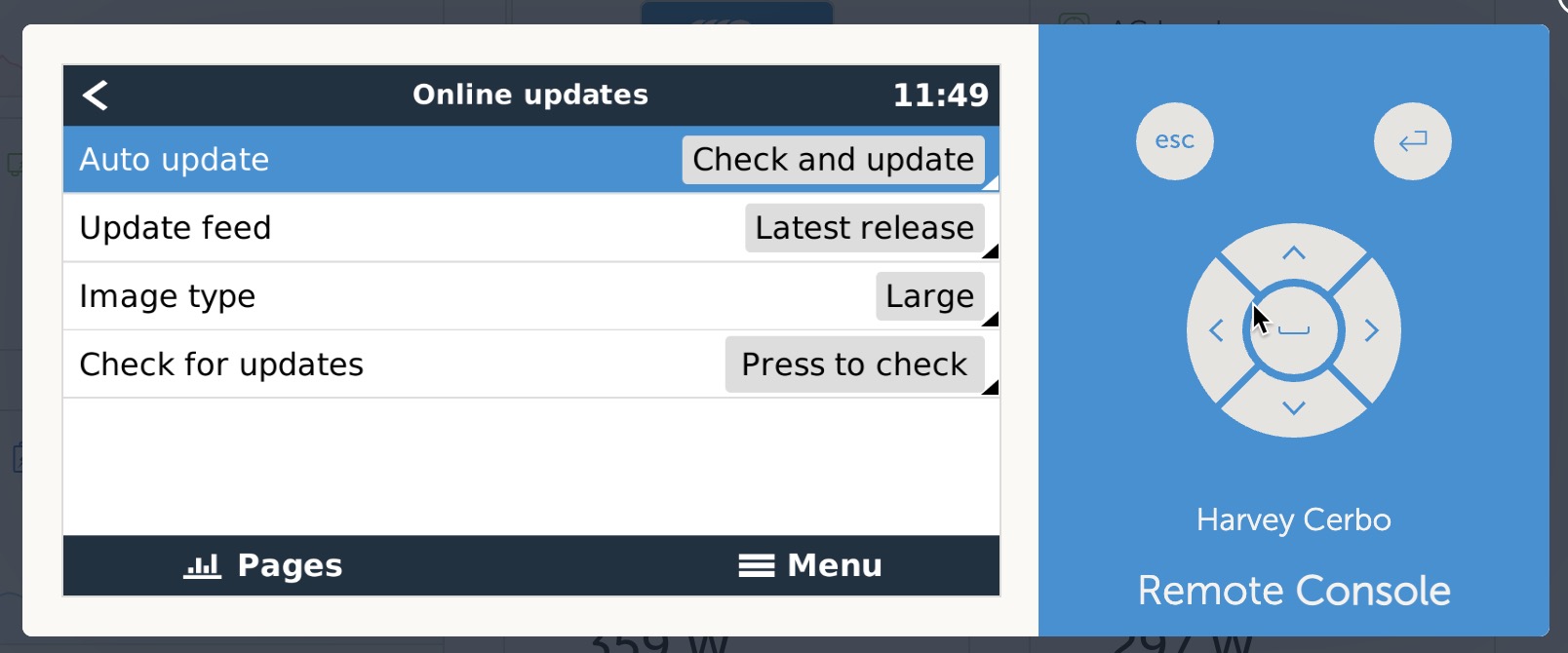
While exploring the best options for controlling the system I was reminded that the large distributions of Venus OS include Node Red and SignalK. I’ve had great success using Node-Red and SignalK server so I was pleased to get back to Node-Red for fine-grained control of the system’s behavior. I’ve experimented with Node-Red and found it to work well and provide relatively easy control of the system. For now, the automatic control provided by the Virtual Switch I described above is providing most of the control I need.
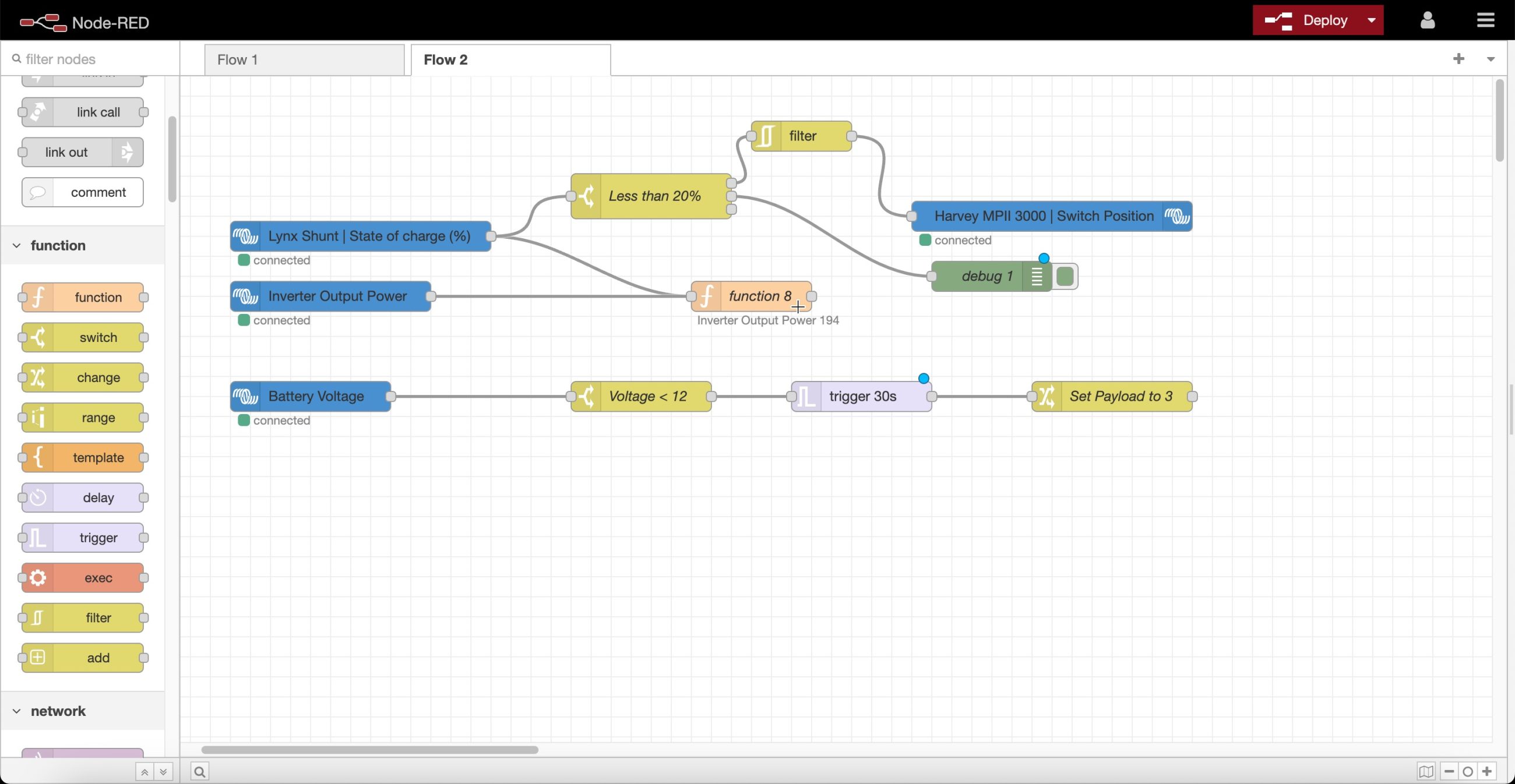
But, during our recent travels, I’ve found one very useful application for Node-Red flows, even with the Virtual Switch handling most of our automation. While staying at a site with only 30 amp power, I didn’t want the inverter to latch onto utility power. Even if they dipped below 40 percent, I didn’t want the inverter drawing power. So, I used the inverter control in VRM to change the inverter to invert-only mode. Thus, it won’t latch onto utility power, even if it’s available and the ignore AC input switch is off.
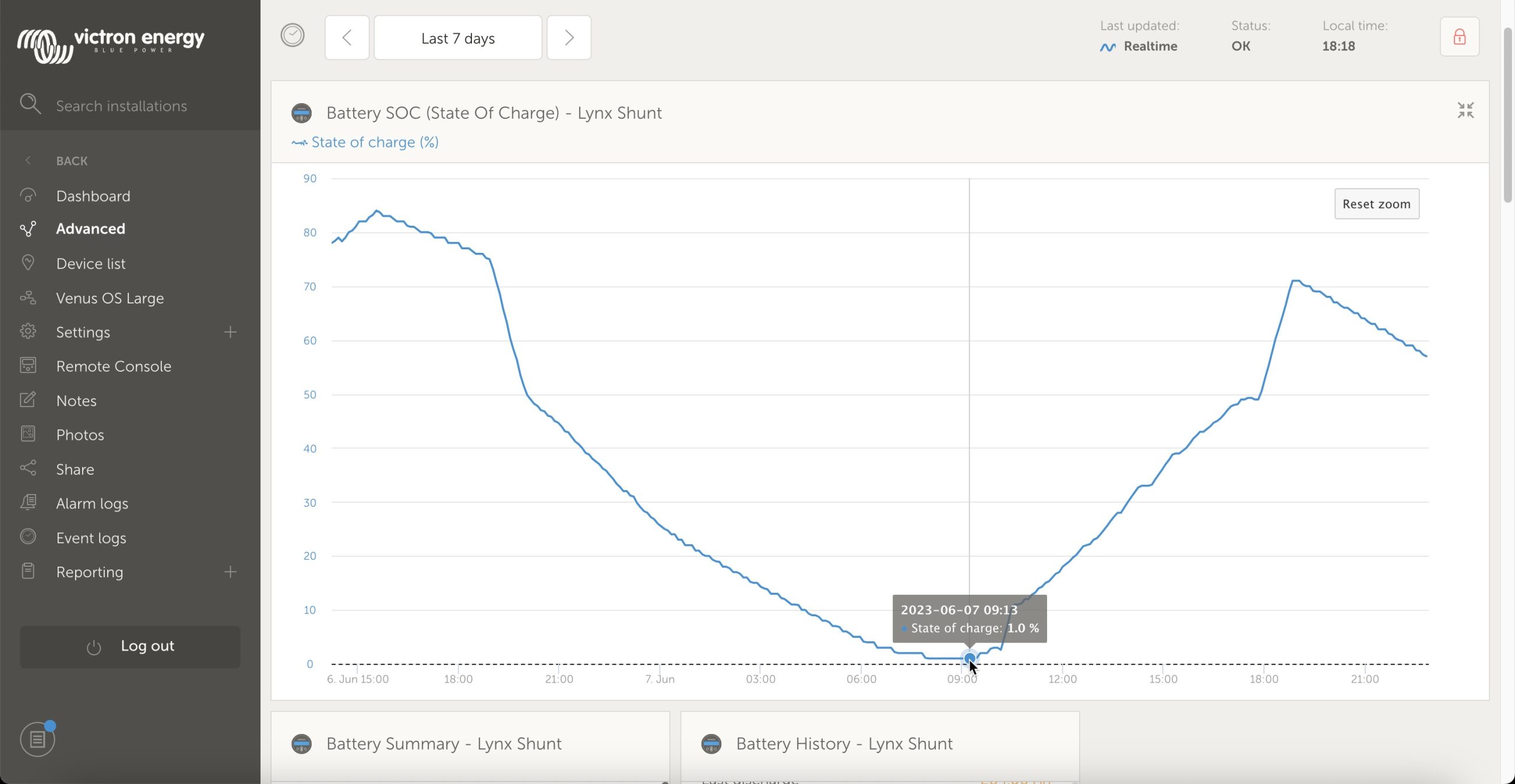
That accomplished what I needed, but I forgot to set the inverter back to on before going to bed. So, I was quite surprised to wake up in the morning and find the batteries at one percent state of charge. Now, I’ve set a rule in Node-Red that sets the inverter back to on. Currently, that’s set to trigger at 20% but I could easily change the percentage or use a voltage reading instead. That change won’t help if we don’t have shore power available, but it will in many scenarios.
Final thoughts
It’s no secret I’m a big fan of Victron’s gear and software. I love the GX ecosystem and the way all the Victron equipment ties together. So, this targetted automation does nothing but enhance my appreciation of Victron’s offerings. To me, this is another example of Victron doing clever things with the information already available on the network and using to add a valuable feature to the system.



I really appreciated the individual slip AC power metering at the Carolina marinas where Gizmo sometimes wintered. That’s because I believe we should pay proportionally for what we use from the grid as a matter of sound public energy policy. Plus I enjoyed paying less than normal flat rates because I’d made the boat pretty power efficient since it usually lives without shore power. But, dang, I never noticed the slick “Virtual Switch / Ignore AC Input” feature though I think it’s been available on Gizmo for many years. It’s small potatoes, I know, but my marina time could have been even less expensive and even less imposition on the grid that needs our tender loving care.
At any rate, nice catch, Ben S. Also, do you see individual power metering in many RV parks? I’ve advocated for it in local Maine marinas, but without success so far.
Ben E, I do see individual metering but for short-term overnight stays, I’ve never seen it used. I think it’s the norm in longer term, like monthly stays. That about mirrors what I’ve seen from marinas in Florida. I agree that individual metering is the right way to go about it, although it does come with some challenges. Many marinas that I’ve come across use the pretty crude odometer style electric meters built into many pedestals. Those can be quite inaccurate. In fact, I saw that inaccuracy at Legacy Harbour (of blessed memory) when we lived there. I’ve also recently seen there are class action lawsuits over marinas overcharging for electric (https://www.classaction.org/marina-electric-bill-overcharging-lawsuits).
-Ben S.
Ben: As a full-time RVer, yes, definitely there are some campgrounds with power metering. Like Ben Stein says, monthly is usually the trigger. I stumbled on all this because I have been … adamant that with my solar capabilities, that should be the priority for topping off the batteries. I’ve been working the last few days to solve why one of my two MPPT controllers wasn’t showing in the CCGX, and solved that, but the only reason I noticed is I’ve been playing with node-red (my own) as well as InfluxDB and Grafana for custom dashboards. Turns out I was behind on my Multiplus firmware updates. (My last version was from 2021.) I figure out how easy it was to update it based on our setup. So I did so, and in that process, leared about the new “Wind and Solar Priority”. But… I’m not a fan, mostly because they only support a voltage threshold, not a SoC, which I think was a good first step, but if that’s the long term plan, then it’s an oversight.
I turned that feature on today when I did the firmware upgrade. Getting ready to head to bed, saw our batteries were down to 60% and the CCGX didn’t show any shore power coming in. I didn’t see any of these Ignore AC *detailed* level setups in the phone app connected to the Multiplus. Maybe I need to use the Windows apps instead.
Hey Ben S. and Ben E. as well, that is an excellent write up. Nice!
We’ve been working on an alternative solution, basically limiting the Multi (or Quattro) to charge up to the float voltage only.
Thereby leaving the rest of charge to solar and wind.
Which of the two options (float only vs. ignore ac input) is best will depend a bit on the system.
I expect most larger systems to benefit most from the ignore ac input one, while smaller systems will be best helped with the float-only solution.
For both I want a user override, so that in case the user does want to charge asap, he can do so with an easy to find control. Rather than having to go into the settings.
Details here: https://www.victronenergy.com/live/ve.bus:skip-absorption.
Its all still in progress. The most difficult challenge has been, and still is, to find easy to understand wording and terminology.
All the best and thank you for that great article!
Matthijs / Victron.
Matthijs,
Thanks for your comment and for taking the time to fill us in on what’s upcoming. You did hit on one of the wishes I’ve had, easier manual control of ignore AC. I’m excited to see that’s coming soon!
-Ben S.
Thanks, Matthijs, and what lucky timing that Ben S wrote about “Ignore AC” for maximizing solar (and/or wind) charging just as you’re developing an alternate method.
“Float Only” charging does seem like a simple and safe alternative, and I certainly see the value of having an easily accessible off switch for either method that’s activated.
I picture, for instance, my boat happily using maximum solar generation in its slip, but then I want the batteries topped up before a cruise starting the next morning. In the Control section of the VRM Dashboard that might be a separate new checkmark line below the Multi control settings that reads “Ignore solar/wind charging prioritization”… or something like that.
Pretty neat.
a great example of the power of Signalk and NodeRed
to fine tune for specific use cases …. which given the multitude of factors and configurations.. some
of which you allude to .. will always be challenging for “even a victron” (very clever folk they are 🙂
to cater for everyones setup.
i have a similar, yet different challenge – to monitor shore power and “intelligently ” switch off and/or alert me of impending overload of shore power circuit … where similarly the very clever smarts and control in Quattro.. get me almost there… but not quite .
.. just love the Victron stuff for its cleverness !
(if only they could improve the “smarts” in the Orion Dc Dc units ….. still waiting 🙂
Greg,
Indeed, I think it’s impossible for Victron to anticipate every user’s needs and wants but, as you mention, Node Red and SignalK give users the tools to help themselves.
And… I couldn’t agree more about the DC-DC converters. I’d love to see them get VE.Direct connectivity and more smarts.
-Ben S.
i have a similar, yet different challenge – to monitor shore power and “intelligently ” switch off and/or alert me of impending overload of shore power circuit … where similarly the very clever smarts and control in Quattro.. get me almost there… but not quite .
For quite some time I’ve manually done this by using VRM to change the inverter mode between on (inverter and charger enabled) and inverter only. When in inverter only, the MultiPlus won’t use mains power to pass through to loads or to charge the batteries. But, wouldn’t it be better if I could leverage all the smarts of my system to not use mains power until the batteries get low? Surely I’m not the first person to want this type of functionality, right?
I wish that the charger-off function (pass through) in the mulitplus, which is accessible only through the mk3 usb dongle afaik, would be an option that is more user available from a cerbo for instance. The reason being, with the multi in pass through mode, you could use solar to cover your DC loads and charge the batts, but use shore for the AC loads only.
This is actually very easy to do–just leave the Multiplus ON and change your AC current limit to 0.0A on either the Cerbo or Multi Control. Multi Control is the easiest as there is a dedicated knob to adjust the AC current limit.
I don’t think that would accomplish what a3n describes. I believe 0 amp AC input limit stops the inverter from drawing any utility power, both for battery charging and for loads.
-Ben S.
Correct, i want AC to be passed through but just turn the charger portion of the multiplus off, which you currently need an mk3 and victron connect for to get into the expert settings
Ben, not correct. AC current limit never disconnects the output. You do need to take steps to have PowerAssist deactivated which can either be directly deactivating it or putting the unit in charge only mode. Either way it will not charge the batteries but pass AC through. I’ve done this many times.
Give it a try!
Ah-ha, there’s the key. If power assist is enabled, this won’t work. In fact on my 3k MPII with assist enabled, current limit can’t be set below 9.5 amps.
Giving up assist would be a nonstarter for me in my use cases but might work for others including a3n.
-Ben S
You don’t give up anything! As I said, put it in charge only—which always means PowerAssist is deactivated—and turn the AC current control to 0.0.
Less than one second to do with a Multi Control and exactly what he’s looking for—AC pass through with zero charge output from the Multiplus. Put the Multiplus back to invert/on, adjust your AC nput current limit, and PowerAssist is back how you had it. Again, less than one second to do on multi control.
Sorry, not trying to be thick. I’d missed the addition in your second message of shifting to charge only mode. If the inverter will go to a 0 amp limit that seems like it should work. I remember that there are variations in the lower limit but not the rules of those variations. I think, but don’t know for sure, that the rules may also be different if controlling with a GX device versus a Multi Control. I’m away from my system right now but will be back later. I’ll try on my system and see if it will let me get to a 0 amp limit.
-Ben S.
Great article! I’ve been wanting to do this very thing for a year now. Like you, I googled it, put questions in forums, and no bites.
However, I have a Multiplus, not a Multiplus II. The II added the virtual switching. Is there a way I can do this with code red and my Multiplus (I)?
Hi Mike,
I believe you would be able to do this with Node Red as long as you have a GX device running the large image. You would likely use value triggers to change the inverter from invert only to on depending on SOC.
Victron’s Youtube channel has getting started videos. Here’s the first in the series for Node Red: https://www.youtube.com/watch?v=i_iaciqn_Fg.
-Ben S.
thank you Matt and Ben,
I tried bringing the limit down to 0.0, but on a multiplus compact 2000/80/120, it will not go lower than 1.0 A. I am controlling it from a cerbo GX
on quattro/multiplus devices, there is a “minimum “ that can be set for the minimum current.
eg on my Quattro … i can only set it to 10A (min), trying to go lower will always default back to 10A.
there is a victron thread (& doc) that provides more info and the limits for each device (apparently is varies between quattro and multiplus, nd across the models)
https://community.victronenergy.com/questions/20956/what-is-the-minimum-input-current-limit.html
The linked document is quite useful. I also noticed the document seems to suggest the exact same thing Matt suggested:
“If you don’t want to use any PowerAssist from your batteries, switch to charger only and now the AC shore supply will still be on and the inverter will be off, leaving that 3.68kW AC shore supply available for DC charging and AC power for any small AC consumers, such as laptops, TVs, a toaster etc.
If you then set the current to zero the charger will be off, the AC supply will pass through and the inverter can’t kick in – handy if away from the boat and shore power fails, as then your batteries can’t be drained by the inverter whilst away. There’s even more sophistication and control if using a Color Control GX or Venus GX, but that is outside the scope of this blog.”
The document does go on to note that you may need a firmware update to fully take advantage of this. So, perhaps a3n’s inverter is in need of a firmware update?
But, it sure does look like Matt’s suggestion should work.
-Ben S.
I’ve been looking for this type solution as well. Even posted to Victron site and didn’t get anything back nearly as elegant as what you’ve outlined below.
In the catamaran setup, most new owners are getting big inverters, large lithium banks, with 1500-2500 watts of solar.
In my use case we moved the boat to the Bahamas and flew back and forth Mar-July. With all dockage having metered power at a cost of 0.65-0.85/kw finding a way to take advantage of our solar during the day and then few hours purely off batteries during the late evening after the absorb charge had completed would have gotten me through ~40-50% of peak power usage while at the dock.
So the latest Venus v3.10 includes the new solar/wind priority mode interface that Matthijs referenced and they came up with effective terminology (I think).
Now you can easily see that your Victron charger is in “Sustain” mode, and quickly switch to Charge mode if needed:
https://www.victronenergy.com/blog/2023/09/12/venus-os-v3-10-solar-and-wind-priority-generator-start-stop-ess/
Unfortunately this only seem to work for a week, then shoreline is used to keep the batteries fully charged after this.
As I look at your settings I have two requests as I am having issues setting it up in my motorhome. !) what is the total PV wattage that you have and 2) what is you battery wattage compacity Thank you for your help.
These settings are from a previous setup but that had 600 amp hours of batteires at 12v, so roughly 7.2 kilowatt hours of batteries and 800 watts of solar.
-Ben S.
So far it’s only for RVs and OEMs, but deep integration between Victron and Garmin looks powerful:
https://www.victronenergy.com/blog/2024/08/16/garmin-integration-offers-rvers-fingertip-control-of-everything/
Ben, love your content! The “Maximizing solar production with Victron GX” was perfect. My only problem is I can´t figure out the proper arlarm settings. I get “276 System overview [276] Grid alarm: Grid lost 2025-02-22 09:36:58 Active” alarm.
First of all thank you for putting this brief together, I found it quite informative. We own a 43’ Newmar and recently changed out of wet cell 8@6V 225AH to 9@100AH lithium with a Magnum 2812. I have been researching changing that out for a Victron device and initially settled on a MultiPlusII. I am all for DIY, but am not comfortable in doing something like this without a knowledgeable technician. So, I contacted a number of Victron dealers and they have suggested the Multi Plus, not the MPII. I am not sure I can articulate the reasons they suggest this, but my needs are simple. I want a device or devices that are capable of charging my batteries in shorter order than the Magnum is currently capable of providing so I can maximize the quiet runtime of the batteries and then quickly recharge; and look at the cost benefit of installing about 1200W of solar to facilitate the reduction of pedestal power when at a ‘pay for electric’ campground. Would you mind sharing your approach to using the MPII versus the MP.
Great and easy idea.
Is it posible to make it so the surplus of solar and wind energie is fet to the grid ?
We live on our sailboat and we feed back in the shore power.
I only found your post in the past couple of weeks after wanting to run my boat with solar first for the past year. Thanks very much for the write up.
I’ve copied your settings in my own installation with a Multiplus Compact inverter/charger. https://wimsworld.wordpress.com/2025/04/16/victron-multiplus-compact-and-solar-priority/
I attended a Victron two-day hands-on training event last year after I had my system professionally installed. I learned the tools and basic installation and troubleshooting, but it seems that installations like this are out of the norm.
Ben, just came across this post a couple of weeks ago. Thanks – its amazing! Ive copied your settings for my setup as Im not a huge tecchy.
I have 660ah agm batteries with an old 3kw multiplus and cerbo gx and 1.8kw of solar.
How did you decide on the measurements for the ignore ac and do you think with my system I should change them or stick with the oarameters you set up?
Estou com problema semelhante, já tentei a configuração do “Virtual Switch” e não funcionou, você poderia disponibilizada a programação que foi feita no Node-Red?
https://www.energy-solutions.co.uk/ introduced SmartSwitch DC4 does not require any special configuration in Cerbo just upload beta software V3.60 …. and the switch are automatically recognized by Cerbo communication via CAN, you can add any amount of SmartSwitch DC4.
https://youtu.be/S4H_qtIe9bk
Correction, we can add up to 5 modules
Just wanted to say this is a spectacular blog post. We have a new Brinkley Model G (full-time RV’ers), and what you described is the exact thing I am trying to figure out myself. Factory installed 800w of panels on the roof, and 400ah of 12v lithium batteries. I’ve been doing the same – flipping the inverter from ‘Inverter Only’ to ‘On’ on good sun days. If we stretch things, in sunlight, we can produce enough power from solar to satisfy all of our ac and dc needs. Another few hundred watts on the roof would keep us super comfortable other than air conditioners.
I simply don’t want to ‘waste’ any of the sun available. Primarily should be used to keep batteries full and power DC loads, but beyond that, I would expect it to shift the remaining available solar ‘juice’ to the A/C side. Ideal state for us:
1. Our Solar realistically can produce 600-650w in the sun.
2. Battery/DC loads should be powered fully.
3. Any remaining ‘sun juice’ capacity should be automatically allowed to pass to support the inverter AC loads.
I can ‘kinda’ do this by setting Grid current limit, but the lowest it goes is 9.4a. I wish I could set this to something even lower. Best path for me would be to be able to set it to 4-5a. Unfortunately, it appears there is no way to set it that low. 🙁 I am now going to dig in deeper to your screenshots and see if I can set this up to best support my personal needs.
This is an elegant solution that I’d like to use but there’s an issue with my Monaco Diesel pusher…
Victron, for some strange reason, sets their inverters to shut off AC2 Out when inverting. I need both outputs when on inverter. AC Out 1 powers about 10 outlets and AC Out 2 powers the Microwave. All are essential when inverting. So what I’ve been doing is using an Assistant to turn on AC Out 2 if the battery voltage is 10v, or higher, for one second. In other words, constantly.
This works a treat but I am also running Solar and Wind priority and found that I really wanted the inverter to also power AC loads where possible. I then decided to follow in your footsteps, but there’s an issue. In order to use a virtual switch it disables the Assistant, which means I am back to losing AC Out2
Do you know of a way to work around this? I have to have both AC outputs when inverting.
Marvin, do you know why the loads are separated on AC Out 1 and 2? The design for the inverter is that loads on AC Out 2 are only intended to be powered when shore power is available. For example, something like a battery charger or hot water heater. In your case, it sounds like you want the microwave to be an always on load and hence connected via AC Out 1. There isn’t any more power available by splitting across the two outputs.
-Ben S.
Yes, Victron made an assumption when they designed the Multiplus, one that limited its suitability for different criteria.
This was not smart design – it’s a built in limitation based on a assumption of how the product would be used.
The good news is that limitation can be overridden by using an Assistant.
The bad news is, if you want to use a Virtual Switch, as you’re doing above, you lose the ability to use Assistants. Apparently the two are mutually exclusive.
This is why I was wondering if you knew of a solution or workaround to have both AC Out’s on, when inverting, and using the Virtual Switch.
Why do you have your AC loads separated across AC out 1 & 2? The basic design of the inverter is that inverted loads are fed by AC 1. What are you gaining by attempting to split that?
-Ben S.
It’s factory motorhome design. Put the microwave on a dedicated circuit, and put roughly half of the outlets on the other inverter circuit.
So those two circuits are not run to the breaker panel, they are run directly to the inverter. This is why the Multiplus 2×120 is so popular as an RV replacement.
Marvin,
Is your inverter a 2×120? You say the inverter outputs aren’t wired to the breaker panel, but are there breakers on the outputs? If not, you have a pretty dangerous setup. The inverter is capable of outputting up to 50a of current on its outputs. If there aren’t breakers on the outputs, you have 50a of potential wired into either 15 or 20 amp receptacles. Basic wiring out of an inverter has either a load side breaker or a sub-panel that ensures the loads on the output can’t exceed their safe current handling ability. That includes the outlets and wiring of those loads.
The Multiplus 2×120 is designed to handle a split phase 240v input. It has outputs for L1 and L2 hots but the switching scheme remains the same. Output 1 is an inverted output and output 2 is only fed when shore power is available. Both outputs are switching two hots and a neutral and those switches are rated for 50a of current.
-Ben S.
Yes, it’s a Multiplus 2×120. No, the outputs on the Inverter go through a sub-panel. Instead of worrying about Monaco’s electrical engineering let’s bring this back to basics, and the original issue, which is the inability to use a Virtual Switch and Assistants and how this relates to your solution outlined above.
I need to have both AC Out 1 & AC Out 2 working when inverting. As mentioned, Victron’s design error, assuming that everyone would want AC 2 Out turned off when inverting, is solved by using an Assistant to turn it back on if battery voltage is more than 10v for 1 second. But when you use VE Configure to set up a Virtual Switch, to use Dedicated Ignore AC Input, it stops you from using Assistants. It’s either/or. It appears you cannot use Assistans and a Virtual Switch at the same time.
So when I implement your solution, I lose AC Out 2 because I’m losing the Assistant. Which brings me back to the original question, is there another way to programmatically turn on AC Out 2 when inverting if I’m using the Virtual Switch?
Sorry Marvin, I’m not seeing an error by Victron. The only point of AC out 2 is that it is switched differently than AC Out 1. There is no more capacity through the inverter by using AC out 1 and 2 or only AC out 1. By having them switch together, you’re defeating the only purpose of AC out 2. So, the solution is to use the inverter as Victron intended. Inverted loads are carried by AC out 1. Uninverted and only shore pass through loads are carried by AC out 2. If you don’t have a need for that feature, don’t use that output. AC out 1 and 2 follow the same path. Each output has its own relay connecting it to the primary AC output of the inverter. The only difference between them is the rules for switching those outputs. You haven’t explained why you need AC out 2. Totally fine to wire it as you like, though I question the benefit you’re deriving from that wiring. However, I don’t want to create an impression for others that AC out 2 somehow does something more than just being controlled by a second relay.
-Ben S.
No worries, you kind of missed the boat on this one, but I appreciate the effort, thank you for trying!
Difference of opinion on that one. You still haven’t explained what you think the benefit is of tying AC out 1 and 2’s behavior together. I suspect that you’re reusing factory wiring without understanding the difference in equipment between what was originally fit on the motorhome and what you have added. I have retrofitted quite a few motorhomes with various wiring schemes but always by considering how best to adapt the original configuration with any changes based on equipment changes.
-Ben S.
It may not be an easy question to answer. I’ll probably have to go to my Victron dealer and have him escalate it up the chain to Victron engineers to determine if it’s possible.
For your own edification, the original Inverter was a Trace Legend Series which had its own sub-panel built in (two 20a breakers, one for each circuit). A brilliant idea when viewed from the perspective of Monaco or any other manufacturer. No need to install/wire a separate subpanel – it’s built into the inverter…saves space, saves time and saves money.
The inverter was fed from the motorhome’s main AC breaker panel and the inverter fed both circuits when inverting. That would be considered normal operation. Because the inverter is powering both circuits, Monaco wisely chose to use one dedicated circuit for the Microwave (for obvious reasons) and the other to feed the other, lower draw circuits, such as the fridge..
This is/was very common, and intelligent design for Monaco (and Trace) back in the day, and it’s also why the 2×120 is often used as a replacement for those inverters. You need two outputs because you have two circuits that need to be powered in the event of a power failure. The remainder of the outlets go dark in the event of a power failure and it’s expected that if you needed them, you started the generator…
To me, it’s rather obvious (read stupid) that Victron CHOSE to shut off AC Out 2 when inverting, and calls this enforced limitation a ‘feature’. It’s based on an ASSUMPTION that limits the product for the end user (as indicated by the Monaco/Trace engineering).
I think Victron realized that ERROR later, and that’s why they gave the end user the option, through an Assistant, to CORRECT that aberrant behavior. That was smart. In my view, better to have left both AC 1 Out and AC 2 Out active during inverting and given the end user the CHOICE to shut one off if desired. That way you haven’t taken any functionality away from your customer.
It’s really a moot point, other than that their CHOSEN operational design limitation, which they inflicted on their customer, is exactly what has brought me to this point. I need to have AC 2 Out active, and it appears that you cannot do this with an Assistant while using a Virtual Switch, because using an Assistant and a Virtual Switch at the same time are mutually exclusive.
It hurts my head just to think about it and convey it in an easy to understand manner, but I think I’ve succeeded ! 🙂
I think when you understand the original design from Trace/Monaco it makes it easier to see why they did what they did, and, more importantly, why it is/was a very good design (at the time).
Interesting side note, because of the Multiplus design, you can actually configure software ‘breakers’ that monitor the AC Out’s and shut them off if they exceed 20A of current. You still need a sub-panel with real breakers in them, but those virtual breakers worked a treat until I found a suitable physical sub-panel with real-world breakers 🙂
Hopefully this will help you understand the overall issue but, as mentioned, I suspect I’m going to have to go back to my dealer and have him escalate the issue, which is, you cannot keep AC 2 Out active with an Assistant if you want to use a Virtual Switch at the same time, as the two are mutually exclusive.
It’s either that or ditch your elegant solar solution as you outlined above, and I’d really like to try it, as I think it adds important functionality that I need – but not at the cost of AC Out 2 going dark.
Marvin,
Thank you, I understand the context of where you’re coming from better now. However, I continue to believe that this should be addressed downstream of the inverter. The old Trace design had some distribution built in with two 20a circuits output with dedicated thermal-magnetic circuit breakers in place protecting each circuit at 20 amps. That’s not the design of the MultiPlus. In a new installation, that’s pure advantage. In your situation, it does require some reconfiguration of your existing wiring. It sounds like you’ve made the first round of modifications by introducing breakers onto the output (needed since you lost the breakers that were built into the Trace). The only other step you have to take is to treat those breakers as a subpanel and wire both to AC output 1. Then, you have what you want. Up to 50a of output (either passing through shore or assisting) feeding those two circuits. Leave output 2 unused or if you have a use case that is aided by receiving power only when shore or generator is available, use it for that. Best of all, once you’ve done that, my solar solution works.
-Ben S.
Marvin, In reading through everything you said only the Microwave is currently on AC out 2. Isn’t the easy solution to just move that one circuit back over the AC Out 1? Since the 2×120 was designed to have AC out 2 only active under certain conditions makes me wonder why you would have put the microwave on AC out 2? The 2×120 can be a bit confusing on why Ac out 2 is there or when its beneficial. It just seems odd that you want to “escalate the situation” to Victron so that they might spend many man hours on a fix for the fact that you put your microwave on AC out 2?
I think Ben nailed it. The answer is just to rewire it. It solves every issue in one shot, and as he said, the inverter can do 50A on that output which is more than needed. It also carries the benefit of faster changeover to inverter (AC Out 2 is a bit slower). It’s also dead-simple so it’s no wonder I missed it.
I have a junction box already in place between the inverter and the panel. It doesn’t get any easier. Tie each of the feeds to the subpanel to AC1 Out in the existing junction box.
But I can still escalate an issue to Victron. I’d like to ask just dumb you have to be to make the Multiplus configurable to the nth degree, and yet, not be able to set an equalization voltage…and yet, have an equalization button in the Cerbo…
Hi Ben – that had never occurred to me!
No doubt, I’m too close to it and have been locked into thinking along the lines of how it was designed from the outset (tunnel vision) to see an outside the box solution wiring solution to the issue.
I’m trying to see if there’s a downside but I can’t come up with anything. That would get it working within Victron’s design criteria and the original wiring design.
Marvin,
Great news, glad to hear another look found the solution. I saw your message to Allen and it sounds like you’ve got the implementation handled too. I don’t think you will come across any downsides, you’re just moving the connection point around and now using everything for its intended purpose.
-Ben S.
Yes, your exactly what I needed – a 3rd party ‘satellite’ view – many thanks for that. I just finished rewiring it.
I do have a concern though, and I don’t know if it’s warranted or if I’m off base. I’m using about 1.5 feet of 12/2 from the AC1 Out to the junction box, which is where the two inputs to the sub panel are joined up using wire nuts.
The potential issue that occurred to me is this, the 1.5′ feed line from AC Out 1 is 12/2 which is rated for 20A (apparently 16A continuous). Yet, as you mentioned, AC1 can actually put out 50A….Doesn’t this mean that the 1.5′ feeder line is under rated?
I’m now starting to think that I should have used 8/2 wire from the AC1 Out and 8/2 wire to each breaker….Don’t tell me I have to do this all over again!