
GFCI and ELCI breakers can be confounding, but heed their warning

I recently met cruisers who have been having trouble connecting their mid-80s boat to shore power pedestals equipped with GFCI (ground fault current interrupters) or ELCI (electric leakage current interrupters). Many months of working with electricians allowed them to plug into some breakers without tripping them but still not others. So, what’s the problem, why did it take months to get it fixed, and what serious safety issues were uncovered? Read on…
In 2011 the National Fire Protection Association changed the national electric code (NEC) to require marina shore power systems be equipped with ground fault protection (GFP). These code requirements only impact new builds or significant renovation of existing marinas. It took states until 2014 to adopt these changes so it’s only been in the last five years or less that boaters have begun encountering marinas equipped with these technologies. Troubles reported from these early encounters led to a revision to the NEC in 2017.

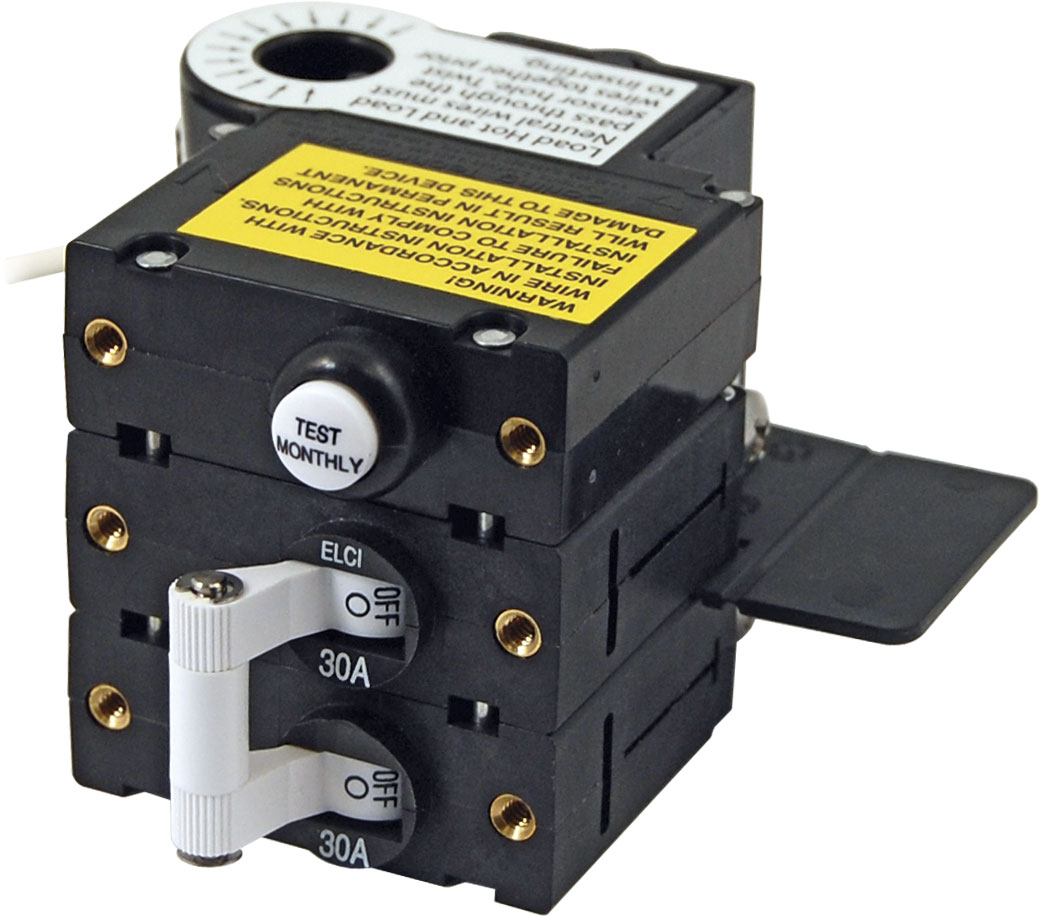
Shore Power Pedestal with ELCI breaker ELCI breaker for installation on a boat

The most recent versions of both the national electric code and American Boat and Yacht Council (ABYC) standards call for an ELCI breaker at both the pedestal and onboard the boat. These standards are only relevant for newly built boats and marinas so it will be many years before the majority of marinas and boats are so equipped.
A serious note
I started off writing this article about the pain boaters suffer dealing with these new marina shore power systems and how to deal with the issues. But the more I was reminded of the basic physics of electricity, the stronger I felt that these systems exist for our safety. I think we all as boaters — I certainly know I am guilty — can become lax about the potentially volatile relationship between electricity and water. Electro-shock drowning is a real and very scary thing. I’ll attempt to stay off the soapbox but please remember that the prohibition on swimming in marinas isn’t because the world is full of fuddy-duddies; it’s because it can be quite dangerous.
The basics
Each alternating current (AC) circuit contains a hot, a neutral, and a grounding wire. The hot carries the electricity to the circuit while the neutral is the return path. Grounding conductors are a safety measure in the event of a fault in the circuit. They provide a safe path for the current to return in the event of a neutral fault and also a means to trip a circuit breaker if the hot conductor becomes exposed.
Though there are many similarities to how a boat and house should be wired there are some very important differences. One of the biggest is that each boat connected to a marina’s shore power system is essentially a sub-panel on the marina’s electrical system. This is an important distinction because a main service panel connected to utility power typically has a neutral to ground bond (the neutral and ground wires are connected in the electrical panel). But, there should only be one such bond in the system so any sub-panels wouldn’t have this bond. This difference becomes a complication when we disconnect from shorepower and start generating our own electricity with either a generator or an inverter.
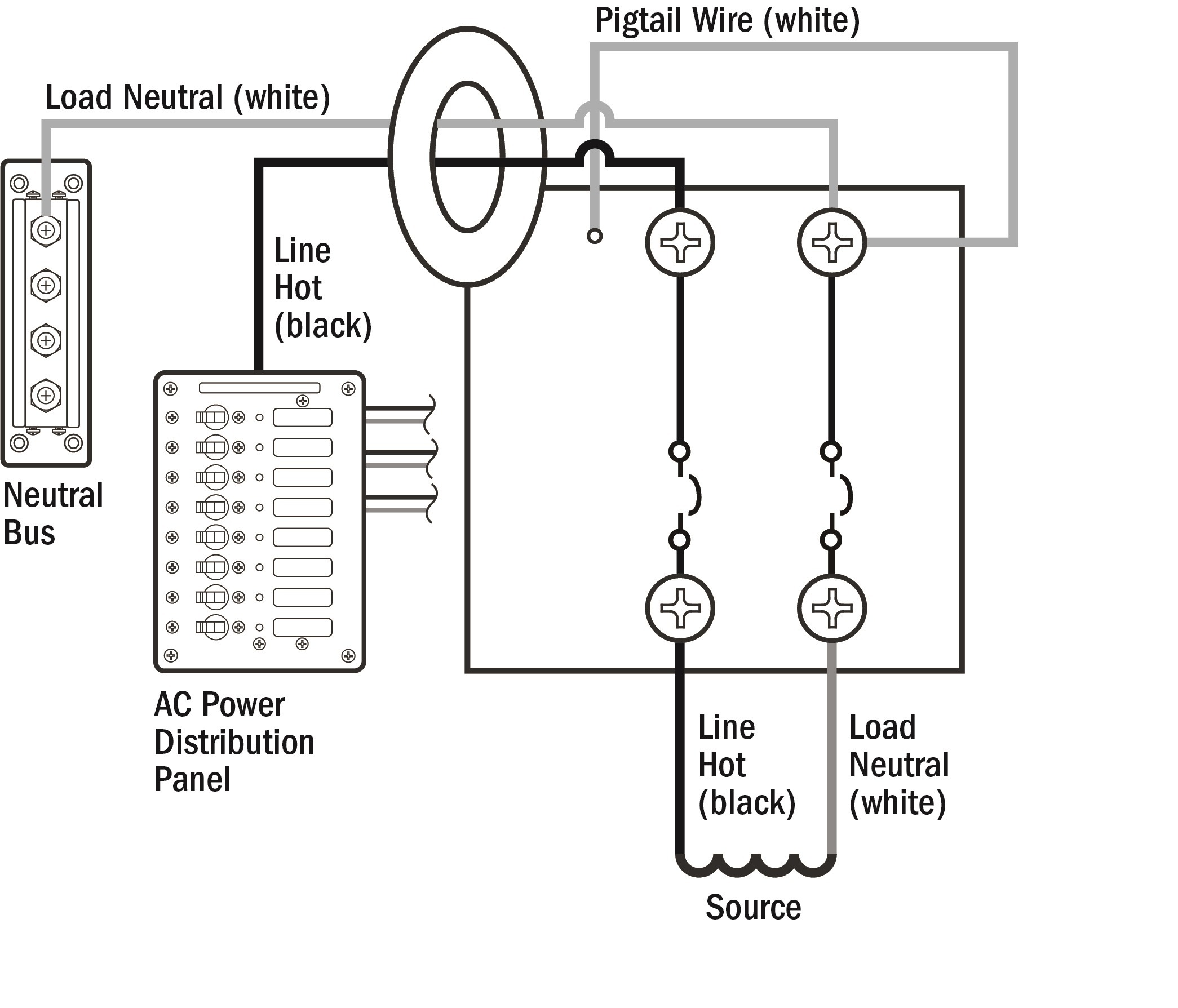
Note: An earlier revision of this article incorrectly drew a distinction between the sensing methods of GFCIs and ELCIs. This was my error, both GFCIs and ELCIs use the same means of sensing — a coil wrapped around the hot and neutral conductors.
GFCI
A point of use 15a GFCI equipped outlet A 50a GFCI circuit breaker to protect a circuit
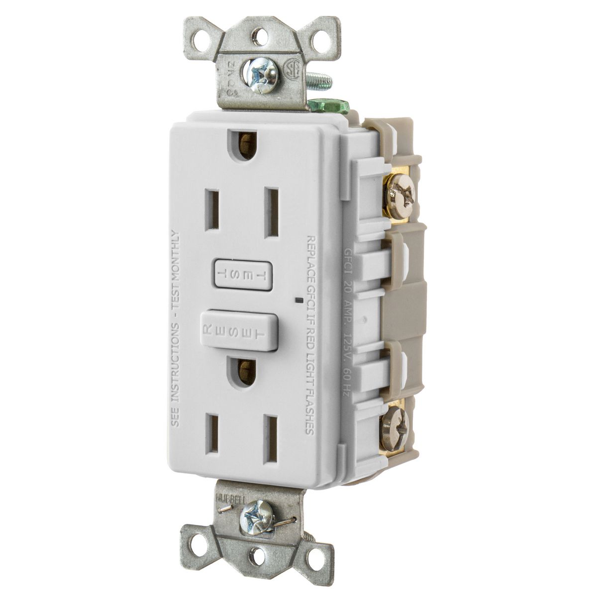
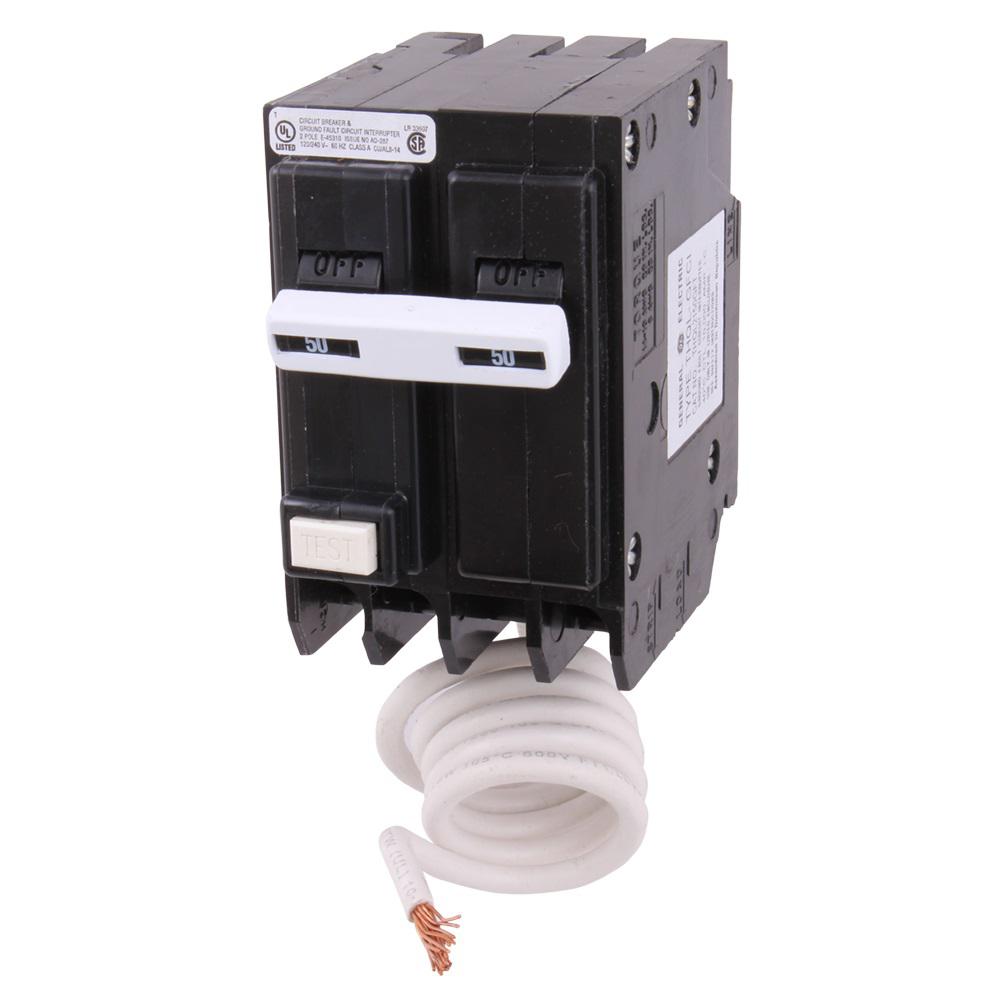
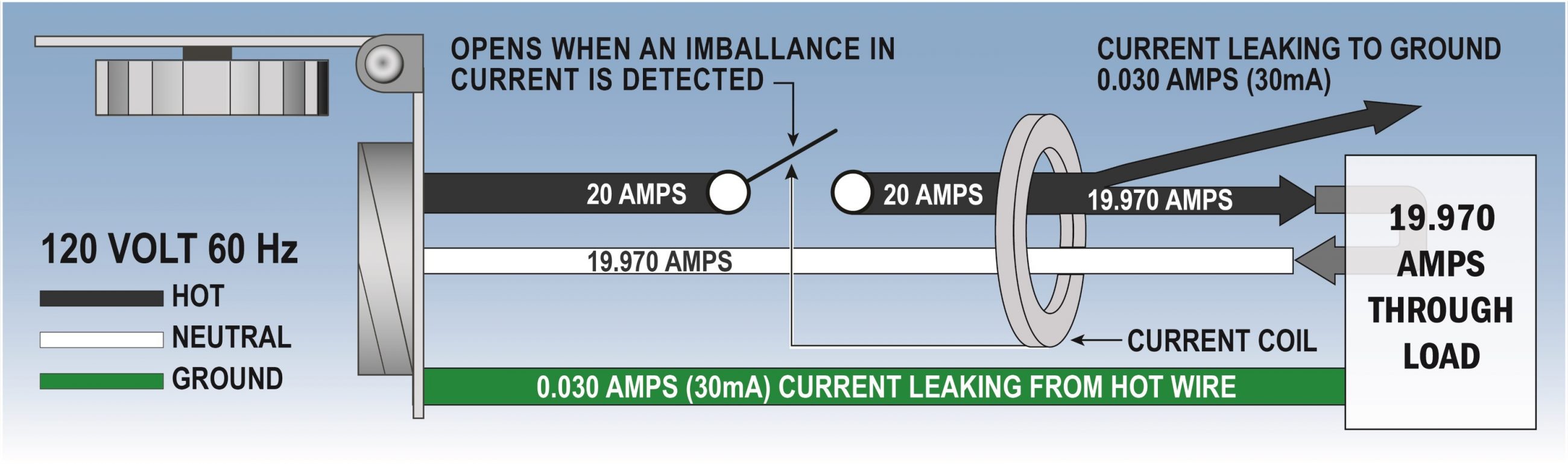
Most people will be familiar with a ground fault circuit interrupter (GFCI) from household wiring where they’ve been required near water sources for more than 20 years. These breakers look for an imbalance of current on the hot and neutral conductors and trip if an imbalance exceeds a threshold. GFCIs will also trip if the load side ground and neutral are connected. GFCIs are available both built into outlets (above left) and in circuit breakers (above right) in nearly all amp ratings.
A GFCI trips when there’s a difference in current between the hot and neutral conductors of a circuit. You may wonder why this is important and if you should really care. The short answer is yes.
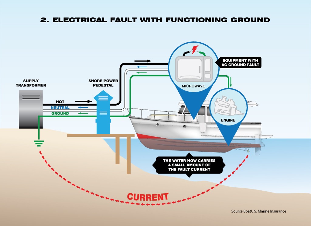
Think of a metal-cased microwave on your boat. Imagine the clip that holds the cord where it enters the case breaks and the sharp metal edge of the case saws away at the cord as your boat is underway. Eventually, that sawing action results in a cut to the hot or neutral wire’s insulation. Now, one conductor is touching the case of the microwave. Fortunately, the case is grounded. So, if the cut occurs to the neutral wire’s insulation the result will be that return current is flowing on our grounding conductor. If the microwave is plugged into a GFCI outlet the outlet will see a current imbalance in excess of 5 milliamps and trip the protection in the outlet. If the hot wire’s insulation is cut a short circuit is created and trips the circuit breaker.
ELCI
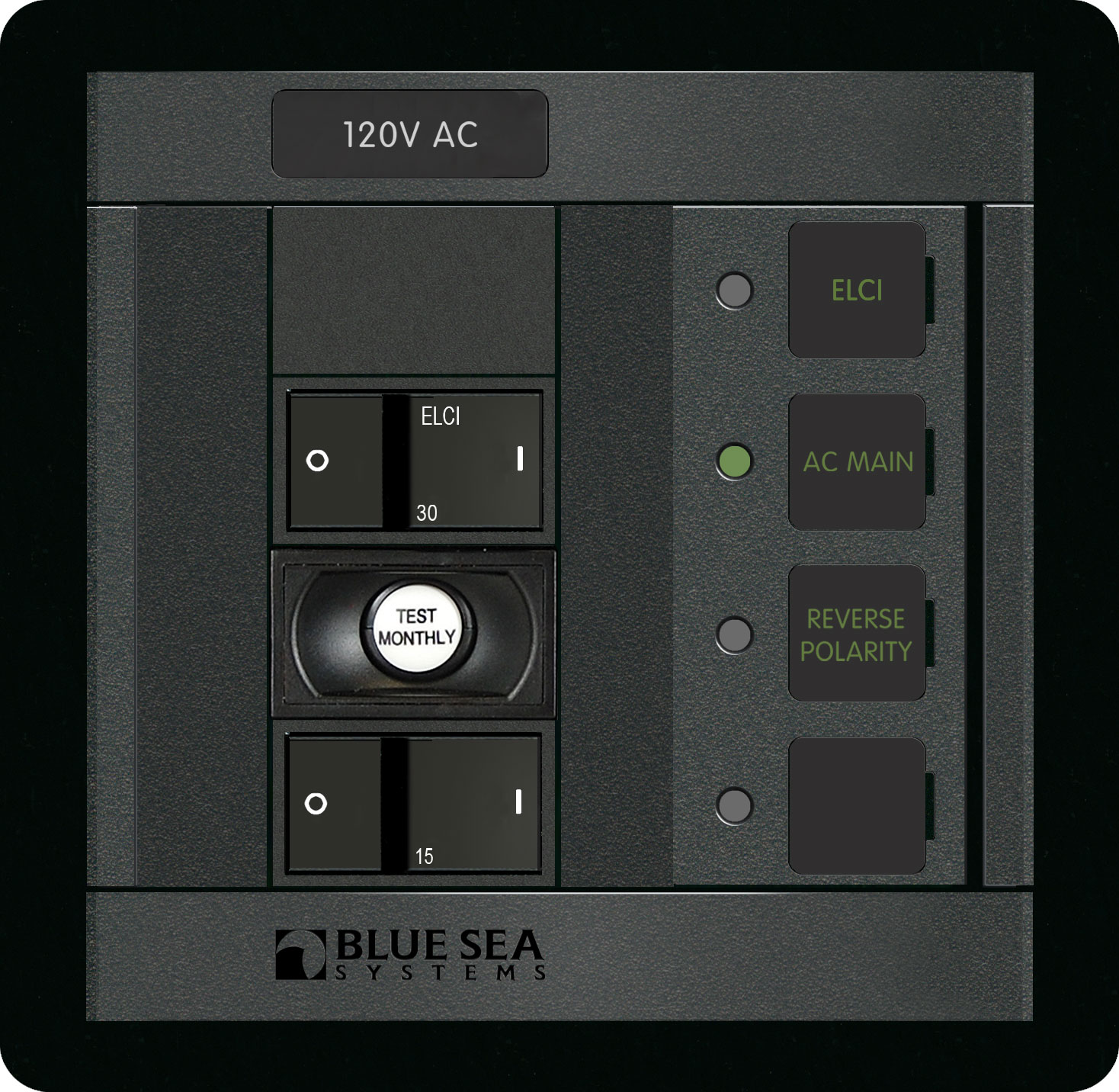
An ELCI breaker appropriate for pedestal use An ELCI panel for use on a boat
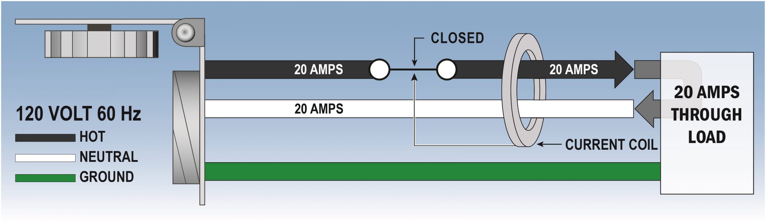
An equipment leakage current interrupter (ELCI) device makes sure that all electricity sent from a shore power pedestal returns. More specifically, the breaker detects any current that is leaking into the water. It also does this by looking for an imbalance in the amount of current traveling on the hot and neutral wires. If less current comes back on the neutral than left via the hot it has to be leaking somewhere. So, the ELCI determines this is an unsafe condition and trips the circuit protection device.
Why is this unsafe? Because even in a properly grounded boat some current will leak to the water via the tie between the AC grounding system and the boat’s bonding system. This current in the water is very dangerous to anyone swimming around the boat and also will cause accelerated corrosion of submerged metal.
The primary difference between an ELCI and a GFCI is the location and intended use of the device. An ELCI monitors all the power going to a boat (if it’s mounted in a pedestal) or coming from shore (if it’s mounted on the boat) and ensures the same amount of current is returning on neutral as delivered on hot. A GFCI protects an individual outlet or circuit.
| Current Level | Probable Effect On Human Body |
| 1 mA | Perception level. Slight tingling sensation. Still dangerous under certain conditions. |
| 5 mA | Slight shock felt; not painful but disturbing. Average individual can let go. However, strong involuntary reactions to shocks in this range may lead to injuries. |
| 6-16 mA | Painful shock, begin to lose muscular control. Commonly referred to as the freezing current or let-go range. |
| 17-99 mA | Extreme pain, respiratory arrest, severe muscular contractions. Individual cannot let go of an electrified object. Death is possible. |
| 100-2,000 mA | Ventricular fibrillation (uneven, uncoordinated pumping of heart). Muscular contraction and nerve damage begin to occur. Death is likely. |
| 2,000+ mA | Cardiac arrest, internal organ damage, and severe burns. Death is probable. |
| Source: OSHA |
ELCIs can be installed both on the shore power pedestal and on the boat. Each installation location serves the same basic purpose but installing one on your boat ensures that your boat won’t ever leak dangerous current into the water and also gives you confidence your vessel shouldn’t have any trouble when you plug into an ELCI equipped shore power pedestal. However, the use of an ELCI for the shore power circuit doesn’t remove the need for individual GFCIs in their typical locations around any potentially wet areas.
Why was the breaker tripping?
As I mentioned above, these boaters worked with multiple electricians to resolve their issues but were still having troubles with ELCI equipped marinas. I was fortunate to visit the boat while it was at a marina — Burnham Harbor in Chicago — with ELCI equipped pedestals — and this was a major factor in being able to determine the root cause. This allowed me to see the issue happen, form a hypothesis about what was wrong and then test it out.
The electrical panel above is original to their boat, but the wiring behind it has been modified in a way that’s not obvious at first glance. There’s now an inverter — mounted in a closet in the aft master stateroom — with its hot, neutral, and ground directly connected to the respective busses on this panel.
The presence of the inverter immediately attracted my suspicion that it was causing the issues. Inverters and reverse Y-adapters are the most frequent causes of ELCI nuisance tripping. A look around the boat revealed there were no breakers to isolate the inverter, so to test this theory I disconnected the inverter from the back of the AC panel. With inverter removed the boat was able to draw power from the marina without issue. Reconnecting the inverter immediately tripped the ELCI.
With the culprit identified the question of why was left unanswered. Some research, contemplation, and discussion with people far more expert than me leads to a theory that makes sense to me. I believe what’s happening is actually a problem of timing.
Remember in the basics section above where I said the difference in electrical systems on a boat becomes a complication when we start generating our own power? Well, here’s that complication. ABYC A31 says:
31.6.7.1.3 – The inverter/charger output neutral shall be grounded at the inverter/charger only when the device is the AC power source.
So this means the inverter has to create a tie between neutral and ground when power is coming out of the inverter and break that tie when it’s coming from shore power. That’s because your boat isn’t a sub-panel any longer as the inverter or generator is the primary source of power. Many inverters do this using relays, including the one onboard this boat. When there’s shore power coming into the inverter the relays are energized and that causes them to break the tie between neutral and ground. But, before those relays could receive power and break the tie the shore power breaker in the pedestal was seeing a fault condition (because of the tie between neutral and ground on the boat) and tripping the breaker.
The remedy
The inverter was installed by a previous owner many years ago and worked fine since it was installed. While it may have worked fine I don’t think it’s been working safely. Fundamentally, I believe this inverter was badly installed and has created some real hazards.
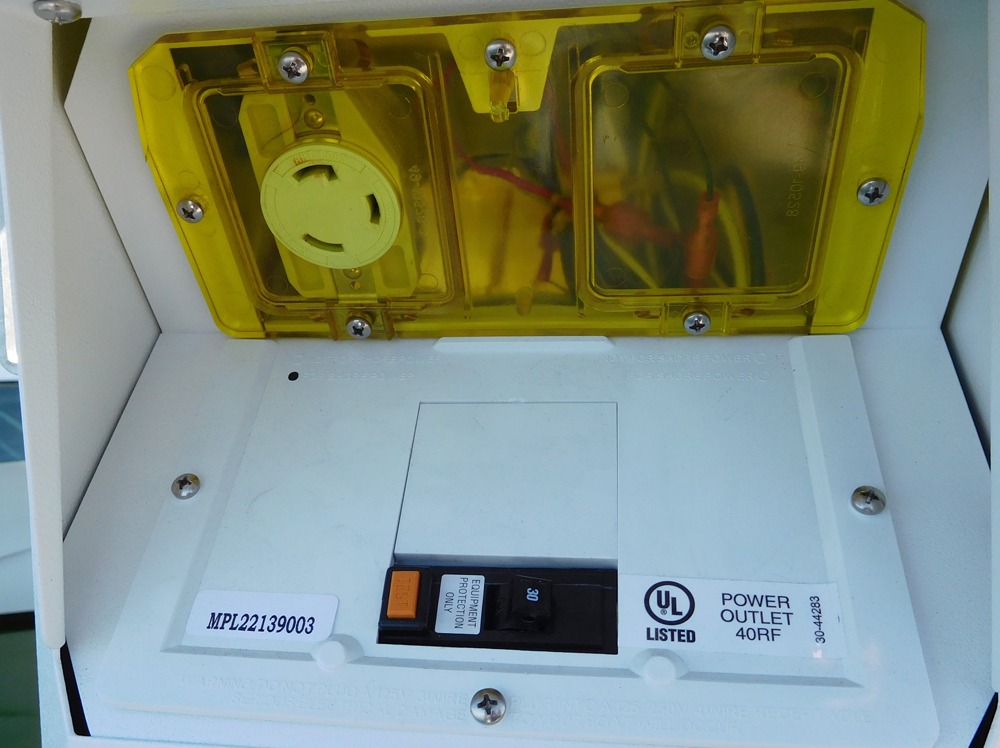
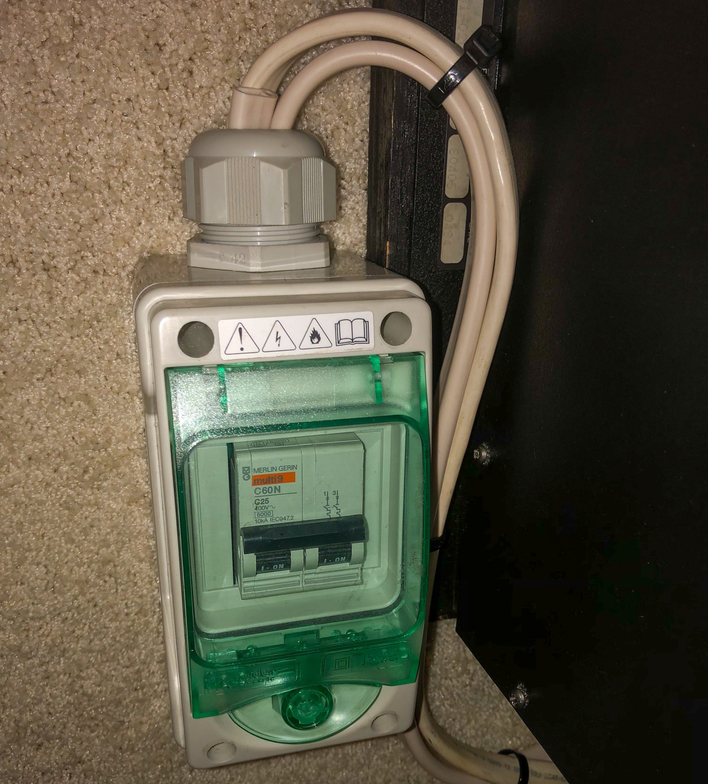
The first step I suggested to allow the boat to draw power from an ELCI equipped pedestal was to add a breaker to the output side of the inverter. This allows isolating the inverter from the AC panel which obviates the ground to neutral issues when connected to shore power. It also allows a quick and definitive way to ensure no power is flowing from the inverter onto the panel. The boat owners were able to have a yard install the breaker pictured above the following week.
It’s taken me a while to fully realize the ways in which this installation is dangerous. Because the output of the inverter is directly connected to the main panel there’s no back feed protection so if the shore power breakers are on the shore power cord itself will carry current from the inverter. There is a multitude of other issues with this installation all stemming from an inadequate installation. These issues are best addressed by having a qualified electrician review the inverter installation.
Final thoughts
As I worked through these issues I’ve been very concerned that multiple professionals have been on this boat and over the electrical system. I would have guessed that they would have highlighted some of the issues I saw, but I wasn’t there and I don’t know how thoroughly they went over the system and the particulars of the work they performed.
But, for me, it only takes one read of the story of Lucas Ritz, a 10-year-old boy killed by ESD, to invigorate the desire to call out unsafe conditions. It’s important to mention just how receptive these boaters have been when I’ve mentioned concerns. The safety issues that exist on their boat aren’t there because they don’t care about them, they’re there because they don’t know about them. So, although their tripping of shore power pedestals wasn’t because of current leakage into the water, it certainly did highlight some very important issues.
Additional Reading:
- Waggoner Guide’s very helpful guide to ELCIs and GFCIs.
- Steve D’Antonio’s primer on electro shock drowning and ELCIs.
- BlueSea Systems has produced a very informative guide to adding an ELCI breaker to your boat.


Mr. Stein, thanks very much for a clear and compelling explanation of this important safety technology. As both a sailor and President of Underwriters Laboratories I applaud your efforts in helping to spread the word about marine electronics safety. We added ELCIs to our own boat and are very glad we did.
Good information, but incorrect about how a GFCI works. You state “These breakers look for current flowing on the grounding conductor of the circuit and trip if current exceeds a threshold ”
The grounding conductor has nothing to do with the operation of the GFCI. A coil around the hot and neutral wires detects any imbalance between the two and trips the device.
You can install a GFCI on an ungrounded circuit and it works fine.
BTW, really enjoy Panbo. It’s one of my favorites.
Mark is absolutely correct. In my research for this article I misunderstood the means of detection for GFCI. I believe that’s been corrected in the article and noted. But, I really appreciate the correction.
Ben S.
Can you please explain to the uneducated how installing the breaker isolated the inverter output from the A/C panel.
If the breaker is on (closed circuit) the current will flow to the panel as if the breaker wasn’t there?? Do the owners have to trip that breaker (open circuit) manually prior to plugging in shore power? My wife and I are friends of these boat owners and were following with interest. We all appreciate that you were able to help them resolve this issue.
Jim,
You’ve hit the nail on the head and I should have been clearer about the fix. The breaker allows isolating the inverter from the AC panel by turning off the breaker. It’s likely that will only be required in a relatively small number of cases (when an ELCI breaker is encountered) so while it might be inconvenient it shouldn’t be frequently required.
The longer-term fix likely involves separating the output side of the inverter from the main panel.
Ben S.
Thank you Ben. This assumes a stand alone inverter? How would this be different if it were a inverter/charger? Would you still be able to isolate the inverter output to the a/c panel without interfering with the charging operation. Appreciate the response.
The breaker is only controlling the AC output of the inverter. So, the inverter is still getting AC power and still connected to the batteries. This means it will still be able to charge the batteries.
Ben S.
Mr Stein – I have a similar nuisance tripping problem on my boat. Is it possible for me to contact you directly to discuss it? I also have had multiple qualified electricians on the boat with no resolution. I need to be sure my boat is safe.
RCD ( residual current devices. ) have been common in Europe for decades now and are routine in marinas and on boats. Any onboard AC generation must be isolated from any incoming shore supply system , either by (a) seperated unconnected systems (b) manual switch over systems that disconnect all three wires or similar automatic solutions that detect invertor /generator power up. It’s easy to do
If I think I get your description right, was the inverter output tied to the entire Bus behind the panel? If so that’s was and still is very problematic. The model of inverter might be helpful for schematic reasons. But let’s say as a worst case the inverter output is wired to the entire bus on that panel and one of say the outlet breakers is feeding the inverter/charger input. For one you have created an interesting loop in the circuit if the inverter has a pass thru relay. But the bigger issue is potentially having the inverter and shore power trying to feed the panel if someone were to shut off the AC feed to the inverter (again assuming a pass thru) Unless the inverter is a synchronizing (and even if it is I doubt this would work correctly) type there is some potential for serious issues as the two AC sources would not be likley to sync.
Take a look at Victron or Magnum wiring diagrams to see the potential issues on not either having a dedicated inverter section a entire panel pass thru or interlock in place.
I have seen a whole lot of bad inverter installs over the years. It seems to be one of the most commonly misunderstood type of installs. I have even seen pro’s get tripped up on really complex systems.
You do understand the description correctly and I share your concern about the wiring configuration. Because I didn’t disassemble all of the wiring it’s possible the point of connection for the inverter is further upstream, perhaps it’s connected to the input of the shore power, not on the main panel, but regardless the danger of multiple AC sources is present. It’s because of that danger that I’ve suggested a competent marine electrician be consulted to suggest a remedy to the current configuration. In the meantime the breaker on the output side at least allows for the isolation of the inverter output.
Ben, this is a good explanation. One thing I might add is that as marinas update their dock wiring and have to be compliant with the NEC code, we’ve found some are misinterpreting the rule and are installing 5-mA ELCIs instead of 30-mA ELCIs. Apparently, you can buy 5s at big box stores and 30s have been harder to locate. We’ve found that it is possible to find all the leaks and get boats below 5-mAs of leaks, but it can be a challenge. Bad inverter installations are the biggest culprits followed by neutral to ground connections in home-style appliances (like washer/dryers), bad shore power wiring, and the occasional failed water heater element.
Given the likelihood that many AC Devices will have EMI filters which in effect feed small currents into the earth lead ,my experience is getting the overall leakage under 10mA can be quite a challenge . For this reason in Europe , whole house RCBOs are rated at 30mA and are very widely available and cheap ( 10-20 euros ) with a standardised set of characteristics type B C D , which are to do with inrush ( as an rcbo is also a breaker )
Less then 30mA RCBOs are very specialised and hard to source , and are mainly used in things like outdoor extension cables and the like
In my marina there are now 5 RCBOs between my boats outlets and the incoming marina supply , making it an “ amusing “ activity tracking down which has tripped , as the discrimination in RCBOs isn’t granular enough to cope with this many and most electrical installs don’t bother sorting out discrimination anyway
Dave,
In the US most electrical ELCI/RCBO are placed in the branch circuits or at the plug hence the 5ma trip settings. As you mention many European installations look at it differently. That’s one of the reasons the ELCI rule caused some headaches in the US. GFCI (5ma) are common (30ma) were used mostly in specialty industrial wiring (from what I understand) until the ELCI rule came out.
Excellent article and excellent contributions from commentators. One thing I have seen frequently with inverter installations is that the output neutral is connected to the common neutral of the panel. The output neutral of the inverter must have it’s own neutral bus that serves inverter loads. When in pass through mode the neutrals a connected together by a relay. When in invert mode, a relay parallels the ground to the neutral. The grounding conductor(green wire) is NEVER to be interrupted by any sort of switch. Side note: A galvanic isolator is not a switch device, it is a pass through device.
Also. ABYC techs and other electro techs out there, Sign up for the 45 hour NEC course. These are given 100’s of times a year all over the country and on line too. Google Mike Holt. The courses are low cost and often free. Contact your electrician or state agency for info. Electricians take protection of life and property as their sacred mission. The National Electrical Code is their Bible.
Have to agree with Alden above. The neutral causes alot of confusion for installers. It also sometimes leads to some odd installations, that may be done right but look strange. If your doing an install I recommend clear labeling, to avoid future issues.
I meant 100s of times a year.
” Inverters and reverse Y-adapters are the most frequent causes of ELCI nuisance tripping”
You mentioned reverse Y-adapters as a major cause of RCD tripping, but no comment on how. What causes the typical problem with the Ys and how do you fix?
This looks like a great place to post my similiar problem. My boat (J/109) never had such a problem until it was hauled two weeks ago. It is now on shore and when I plug into the marina’s 15 Amp outlet (from GFCI 15 amp outlet, to a normal 15 Amp extension cord, to a 15Amp-30Amp Adapter, to the boat. I used two different extension cords, I used in prior years, problem recurs with less frequently than the other. In either case,no problem if I use a power tool, but the breaker is subject to tripping when plugged into the boat with a load only of the shore charger on a mostly charged battery.
What’s the charger and do you have a isolation transformer(I know, unlikely) or a galvanic isolator?
Charger, ProMariner ProNautic 1230P 30 Amp 3 Bank Battery Charger
Galvanic Isolator, Promariner ProSafe One
Isolation Transformer, No
Ah, yes. The ProSafe 1. I’ve seen this a couple of times and I know another sparky who has seen this. I think there was a self test feature in that model that momentarily looks at the ground f in some way and it is enough to open the 15A GFCI. I don’t know if the newly NEC required(in new installations) 30A and 50A pedestal GFCIs suffer the same problem. BTW the PS1 has been discontinued for quite sometime. Consult with an experienced electrician.
Many Thanks Alden Cole. That looks like a very promising direction! After searching on that clue, I see someone has written that the ProSafe One self-test (not a problem for me until this first yard) can be temporarily disabled with the removal of a fuse for the winter, which would provide a great short term answer.
Perhaps a new galvanic isolator is in my future if I run across more outlets like this.
Ben – perhaps you want to make a note of this inside your article above?
This is good information and I’m glad it’s noted here. I think most readers with similar problems will scroll down and read the comments. There’s a number of interesting anecdotes of similar issues in the comments and I think that’s a good spot to capture them all.
It would seem like one is asking for trouble if you connect your inverter to the entire boat including the shore power input.
Typically one only uses an inverter to supply AC to a subset of outlets on board the vessel. An inverter is not a gen set and is not intended to supply and entire vessel with AC power.
Way too much room for human error here that could be disastrous not to mention that when you have an invertor it will never be in phase with shore power and things are bound to blow.
Dan, I think that many modern inverter/chargers are designed to pass through shore power as needed, and then auto switch to inverter mode for some loads if shore power fails. I know that my Victron Mulitplus will switch so fast that a PC running on AC will just keep running.
The Multi can also limit the maximum AC shore power amps being used, which was great last winter when I used an adaptor to plug the boat’s 30amp cable into a standard boat shed 20amp wall outlet.
I agree that there are inverter/chargers that have a transfer or pass through feature that will auto select only one AC source that will be presented to the vessel. As for your PC test is the PC a laptop?
If it is then its battery will isolate or make the power drop out transparent to the laptop’s operation. So that is an invalid test. If you were to remove power momentarily from a desktop PC I doubt that the PC would remain stable throughout the power dropout.
However I think you miss the main point that if people are connecting inverters outputs to the shore power input of the vessel then you are putting into potential peril the entire boat and all of its crew. It is just like having your genset and shore power connected simultaneously.
You could have a fire due to phase conflicts between inverter and live shore power or you could have the death of crew if there is a ground fault and the ELCI will fail to isolate the boat from inverter if the ground is not connected to the neutral of the inverter ac output.
Vessel owners should know what they have and enlist professionals to ensure the electrical safety of your vessel if you have an inverter whose installation is suspect.
Dan,
I do exactly what’s described regularly with a 17 year old Charles Industries (made by Vanner) inverter. I have multiple PCs (primarily Intel NUCs without a battery) onboard that weather the transition from shore power to inverter to generator and back without any issue.
As to the many ways a boat’s AC system can be modified to make it dangerous, I agree and try to point out those dangers when I come across them. Probably the scariest modification I’ve ever seen was a boat with port and starboard shore power inlets. The rotary selector switch failed so the owner simply bypassed the switch and connected both inlets. So, if anyone ever touched the lugs on one inlet was in use, a 240v 50a shock would follow. The ease with which someone could lose their life was frightening.
-Ben S.
-Ben S.
Thanks, Dan, but I understand that a laptop would be an invalid test. What I had for years on Gizmo was a Mac Mini running on AC straight from the inverter or shore power.
My boat is 20 years old and I suspect it has always had the AC panel marked with a warning “This panel serviced by inverter”. I know it was there ten years ago when I bought her, and all systems were checked out as good by a surveyor and other experts. And checked again when I replaced the existing Xantrex inverter/charger with the Victron.
I think that maybe what you’re missing about this sort of setup is that the inverter/charger and shore power (if present) are always connected simultaneously to the AC panel, with the inverter/charger doing the source switching as needed.
As Ben E. mentioned many newer inverters are designed to be an integral part of the shore power system with load shedding, shore power backing capabilities. But, I do also fear there are many boats running around with potentially dangerous installs where the output of the inverter is simply connected to the bus bars of the AC panel. While this configuration can work, it’s potential for dnager is real and the need for careful management by the user is much greater.
-Ben S.
I just noticed that Peter Kennedy of PKYS posted a thorough “Installing your Victron MultiPlus Inverter Charger” how-to, even including ABYC references:
https://shop.pkys.com/Installing-your-Victron-MultiPlus-Inverter-Charger_b_88.html
I would like to add to Ben E’s link to Peter Kennedy’s post. Victrron has a page with white papers on various subjects. https://www.victronenergy.com/support-and-downloads/whitepapers. There is one on power assist where the inverter will phase synchronize to say, utility power, and partially power to the load. A particularly interesting one for power nerds is the generator shoot out, https://www.victronenergy.com/upload/documents/VE_Marine_generator_test_RVA_07-jan-2008.pdf. The testing is a real ball buster. This system could be used for solar/wind charging sources with battery systems where the batteries provide inverter power and the utility picks up the slack.
I don’t seem to be able to print this article full page , I’m only able to get a thin center column, can you tell me what I am doing wrong? sorry, a newbe
Not sure what your print setup is, MKB, but often the best way to get you want from a complex web page like this one is to cut and paste something like this entry column into an email or doc file, and then printing it.
Would use of a double pole disconnect switch be acceptable as a disconnect means for the Inverter AC output, or is a circuit breaker required?
If the requirement is to disconnect the inverter output, a disconnect switch is fine. But, if you need overcurrent protection, you will need a breaker. If there’s already overcurrent protection in the circuit, then a disconnect is adequate.
-Ben S.
Are there any reverse y adapters that have been engineered to work with GFCI/ELCI outlets? My Marinco reverse Y trips the breakers every time and they (Marinco) have told me that is to be expected. Not terribly helpful.
And the Marinco people are correct. Review the diagram at the beginning of this article. Both the supply line, the hot, and the return line,the neutral, must be equal. If there is an imbalance, as when a portion of the current is returning via ground during an electrical leak such as in the microwave example above, the ELCI/GFCI device will open. The reverse Y has two hots but share the same neutral/return path. The ELCI/GFCI devices won’t be in balance with their respective hots for a number of reasons. A proper isolation transformer might(maybe) work but even that could have issues. Plug into a proper ELCI protected 50A circuit that is designed to work as designed. Are there any EEs out there that can comment?
I see several comments about an imagined problem of the inverter “feeding AC back into the shore power”, creating loops, and other notions. I don’t think this can happen, as long as an automatic transfer switch (sometimes called a passthrough or other names) is present either externally or built into the invertor. Any marine inverter that I know of has this feature built in, but it’s easy to add if not. The transfer switch contacts are double pole, double throw. It selects hot and neutral from either shore or inverter.
As soon as AC power from the shore is applied to the inverter or an external transfer switch then the transfer switch will select it’s input to be the shore power line. This will cause a total disconnect of the inverter circuit. So with shore power applied, the output of the inverter, both hot and neutral, is simply floating and not connected to anything.
When shore power is removed in any way, then the transfer switch selects the inverter AC output, and totally disconnects the shore power connection. But since by definition you have disconnected the shore power in this case, there is no way power from the inverter function can be fed back to shore.
All this assumes you have only the output of the inverter/transfer switch connected to the boat’s AC panel, so there is no way AC can get to the bus by any other connection.
Because sometimes there are loads that are larger than what your inverter can handle, you can have two AC buses. We have a bus that connects only to shore power, and another completely separate one that connects only to the invertor/transfer switch. But that latter bus is powered from shore power when available or inverter if not, as described above. There are no connections from hot or neutral between these two buses.
The issues where you have load shedding inverters , ie in effect grid tied inverters, is quite complex where RCD s are involved.
In the first instance where load shedding isn’t involved the transfer switch should disconnect all three wires , ie including protective earth and the neutral should be connected to the on boat protective earth at the inverter. Any RCDSd should be on the output of the inverter , switching back to shore should completely isolate all three wires to the inverter , the same RCDs being used as before ( ie the inverter is positioned before any RCD )
With grid tied inverters the neutral shouldn’t be tied to protective earth at the inverter , and again the inverter should be “in front” of any boat inverters
A grid tied inverter must have “ anti islanding “ as in the inverter must either switch off when shore power isn’t available or have a robust automatic shore disconnect feature
Tripping the marina RCDs where you have grid tied invertors is very common and can be hard to avoid. In my opinion I would avoid load shedding inverters for that reason as any unexpected return path will cause the shore side RCDs to trip
It’s not helped by US stipulations to ground , ie to protective earth ) AC to boats hardware and or DC negative. This exacerbates the issue , in Europe with RCDs this is not done and not required.
I have read that an isolation transformer will help cure the problem on older boats, what is your opinion on installing one of these?
Thank you
In my view an isolation transformer offers the best of both worlds , increased on board ( abs in water ) safety as well as complete protection from impressed corrosion. The only downside is expense , size and weight , though Mastervolt are doing a switched mode one.
Just ordered one from Bridgeport Magnetics, made in USA, no wait time
Don, did you get your Marine Puck(s) installed? If so, what do you think?
-Ben S.
I did, back in May, I’ve had no issues since then, all is well!
The AC circuit breaker box the yard installed (under “The Remedy”) has a triplex wire sheath sticking out with one cut wire in it. That’s odd to say the least… Wonder what they were thinking with that.