
NMEA 2000 network troubleshooting with Digital Yacht, Actisense, and DIY Tools
NMEA 2000 networks are pretty reliable but when there’s trouble it is often unclear where to start. Digital Yacht and Actisense have both brought out new products to help ensure the health of a network and better understand its operation. But, even if you don’t have any specialized tools onboard, you can still do some basic but effective troubleshooting of the health of your network. Let’s explore Digital Yacht’s NAVDoctor, Actisense’s A2K-TER-U smart NMEA 2000 terminator, and the troubleshooting you can do with an NMEA 2000 breakout cable and a multimeter.
Digital Yacht NAVDoctor
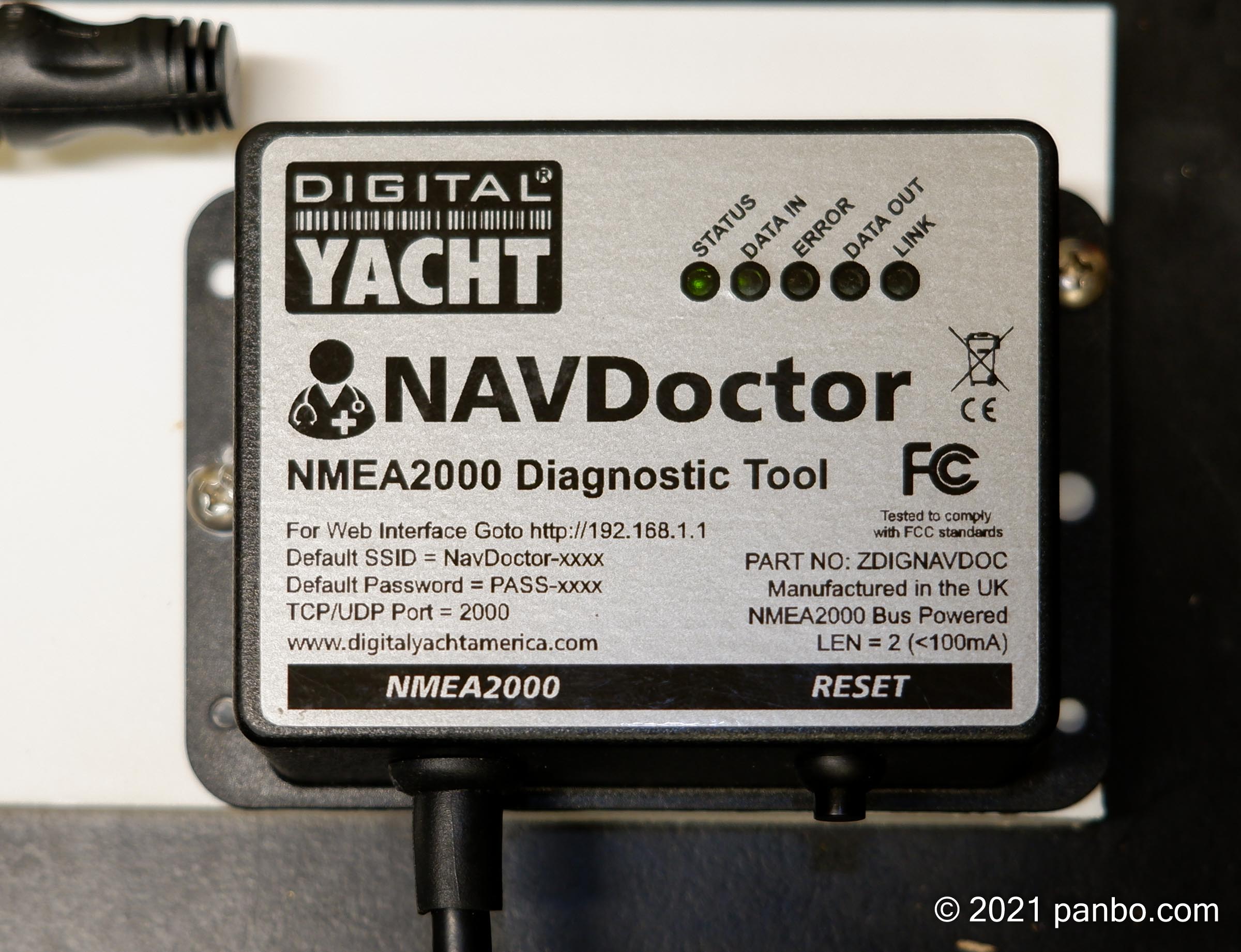
The $450 NAVDoctor aims to make it easy to assess the basic health of an NMEA 2000 network. It’s a standalone device that draws power from the NMEA 2000 network and displays its output via a WiFi-capable device. NAVDoctor measures and displays bus voltages, bus load, errors on the network, and more. It also displays lists of devices and PGNs on the network. Plus, it displays and can log the raw data on an NMEA 2000 network.
In their webinar explaining NAVDoctor’s capabilities, Paul Sumpner, Digital Yacht’s CTO, mentioned the capabilities of Maretron’s $895 N2KMeter. I suspect that Digital Yacht is in part positioning NAVDoctor as a cheaper, easier to use alternative to N2KMeter for many tasks. At half the price NAVDoctor lacks some functionality compared to the Maretron, but also adds the ability to display a device list, decode PGNs, and record the traffic on your network.
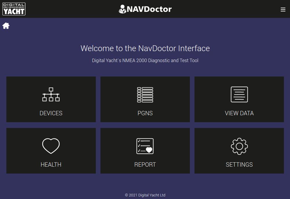
NAVDoctor’s main menu provides access to the five core functions of the unit, plus its settings. The five main functions are the Device List, PGN List, Raw data, Network Health, and Network Report.
Network Health

I found that I used the network health page more than any other function. I also think network health is where NAVDoctor really shines. Quickly and easily getting access to the data provided here is a real advantage. Whenever I hear about troubles with NMEA 2000 networks my first two thoughts are power and termination. Specifically, is the network properly powered and terminated?
The NMEA 2000 spec calls for a 12-volt nominal power supply. But, especially on boats that have had lots of work done it’s not unusual to see big voltage sag at the helm. Sometimes the power being provided to the NMEA 2000 network can be well below 12-volts. That combined with a long network and/or any less than perfect connections can be a recipe for trouble.

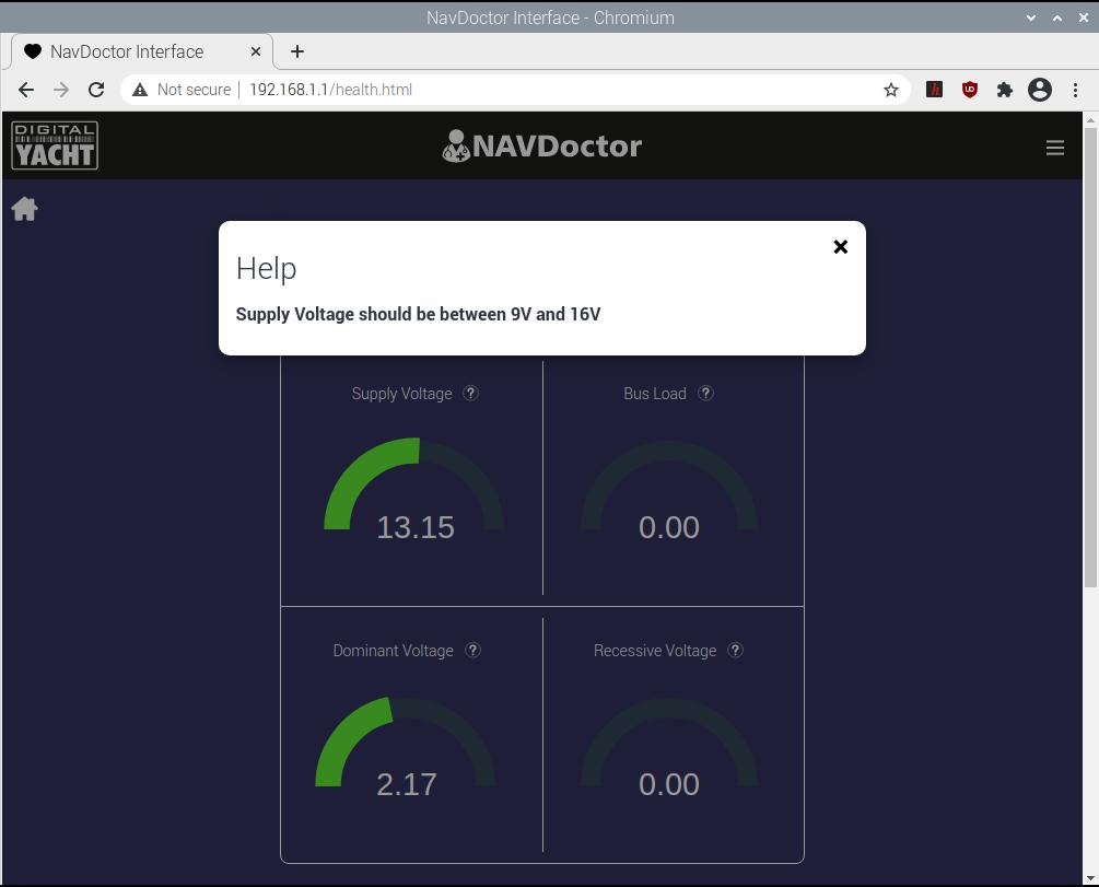
Normal network health with two terminators on the network 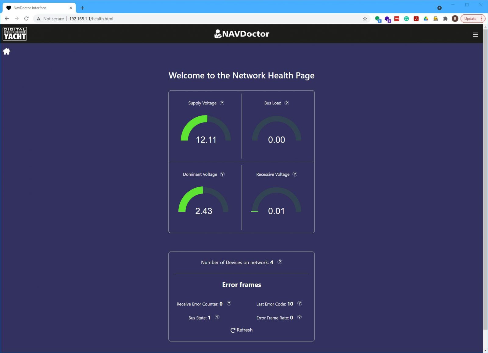
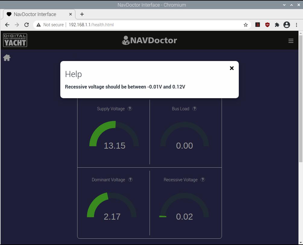
Network health with one terminator on the network 
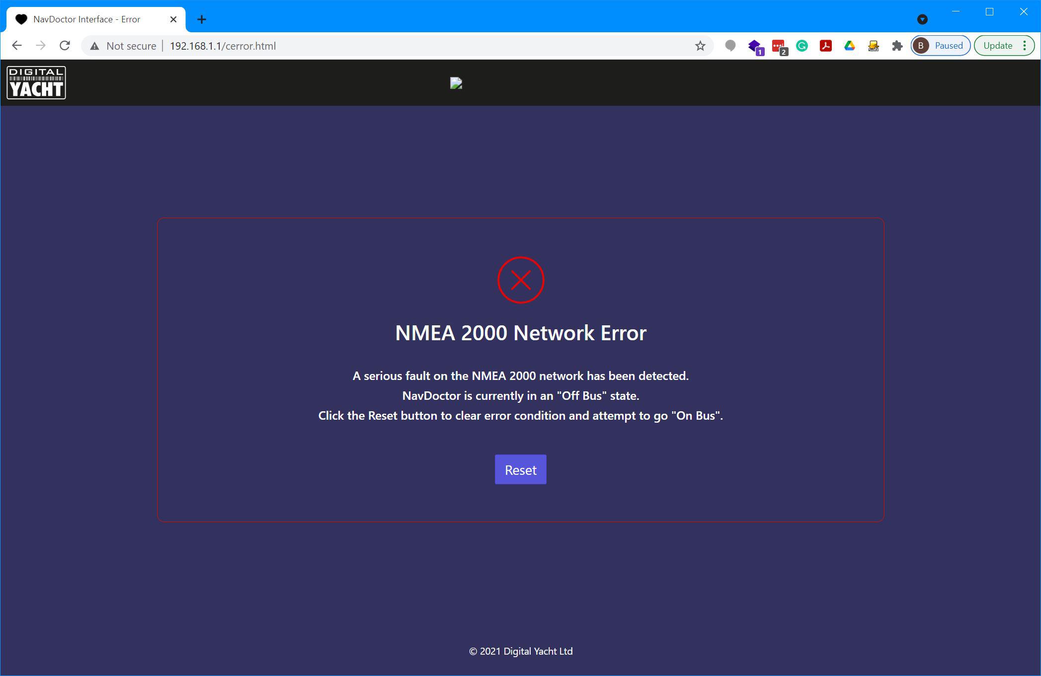
Network health with no terminators on the network 
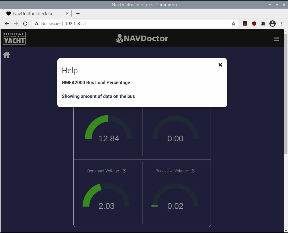
This error eventually popped up when testing the network with no terminators
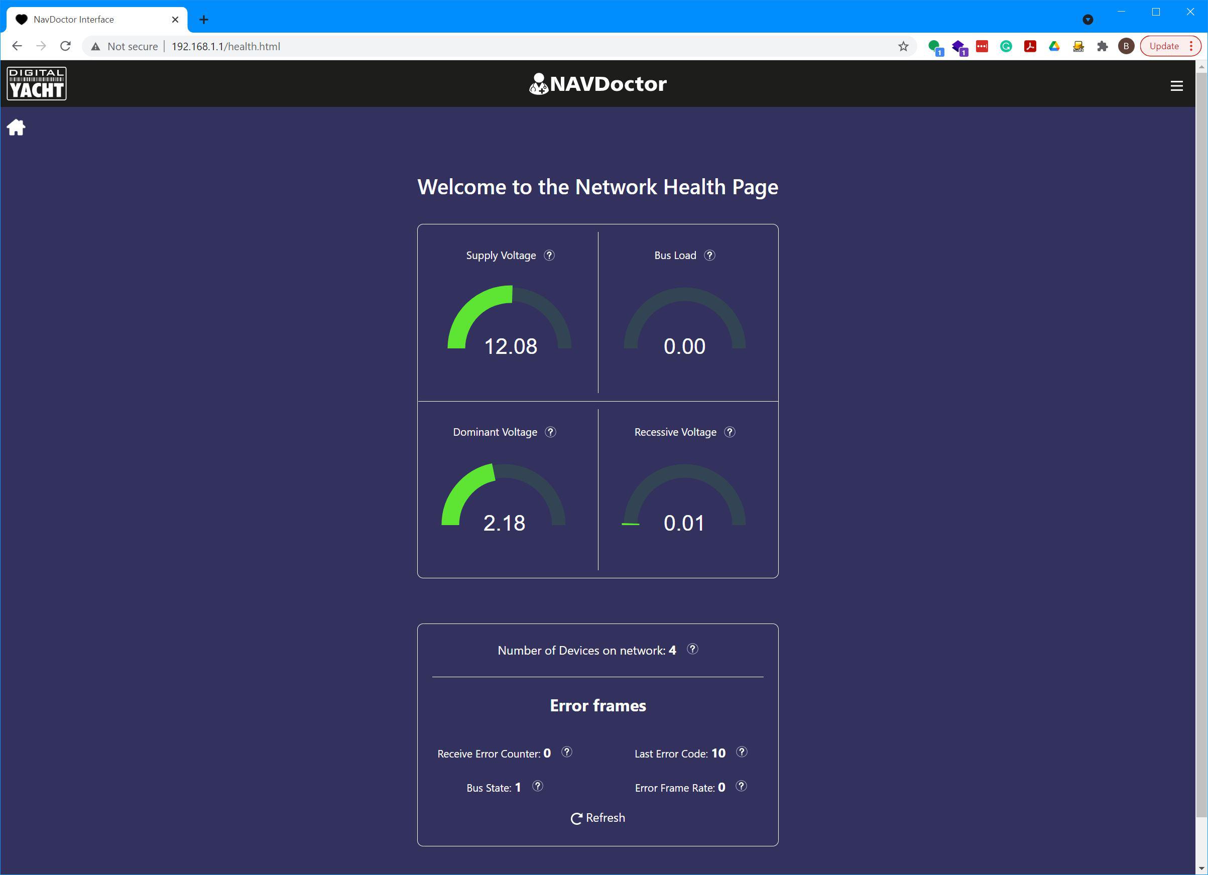
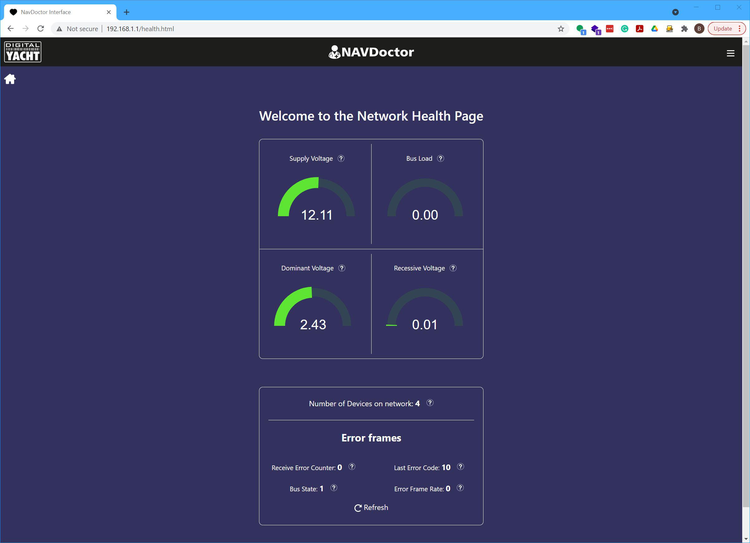

Like all CANBus networks, an NMEA 2000 network requires two 120-ohm terminating resistors. One resistor should be at each end of the network. This means that when a powered-down NMEA 2000 network is metered for resistance across CAN-Hi and CAN-Low you should measure 60-ohms of resistance. But, when the network is powered up improper termination can be inferred from the dominant voltage. As the screenshots above show, not enough terminators will cause the voltage to rise above normal values while too many terminators will cause the voltage to dip below normal thresholds.
Device list and PGNs
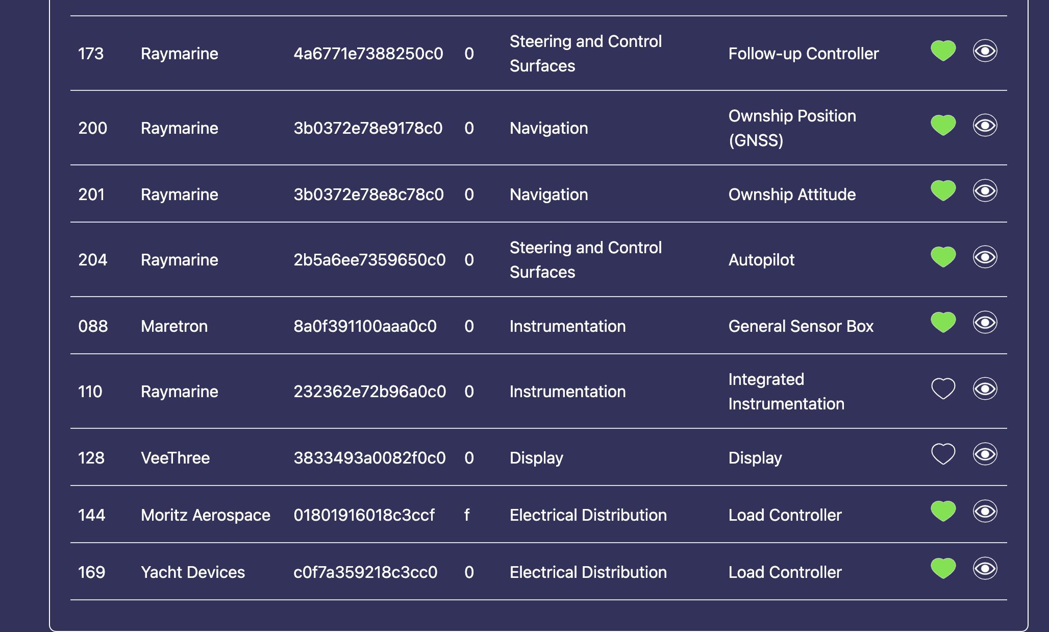
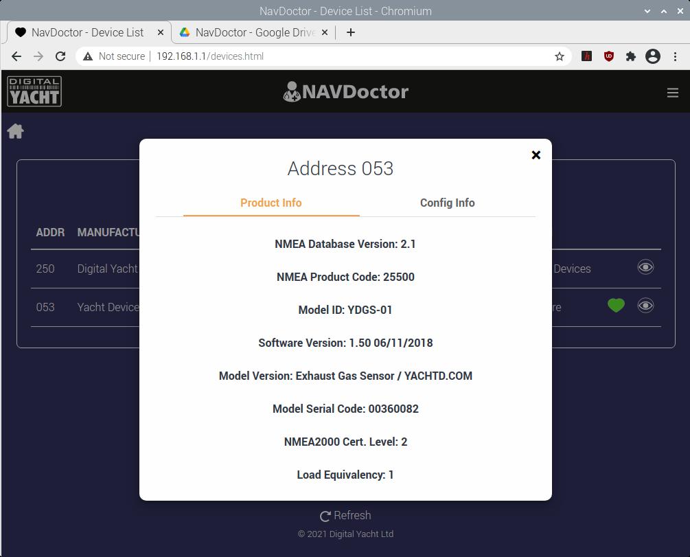
Unlike the multi-meter style N2KMeter or other tools, with NAVDoctor’s web interface, you can dig into a lot more information about the network. NAVDoctor displays a list of all devices and PGNs (NMEA 2000 messages) on the network. Both device and PGN displays give you a summary list and the ability to drill in and see specific information on a device or PGN.
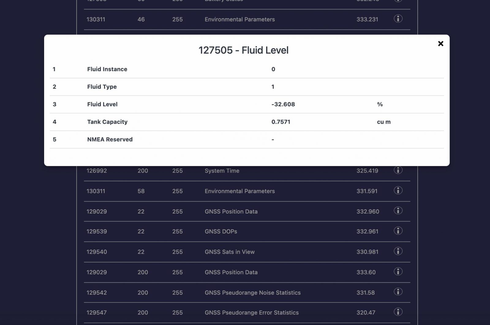
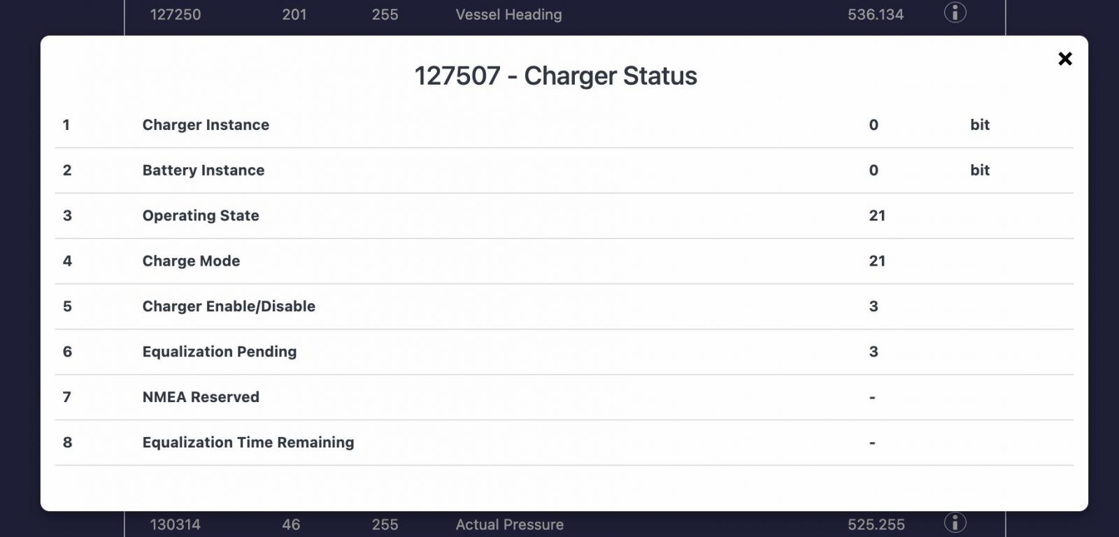
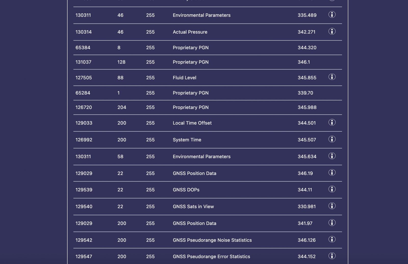
NAVDoctor’s PGN list
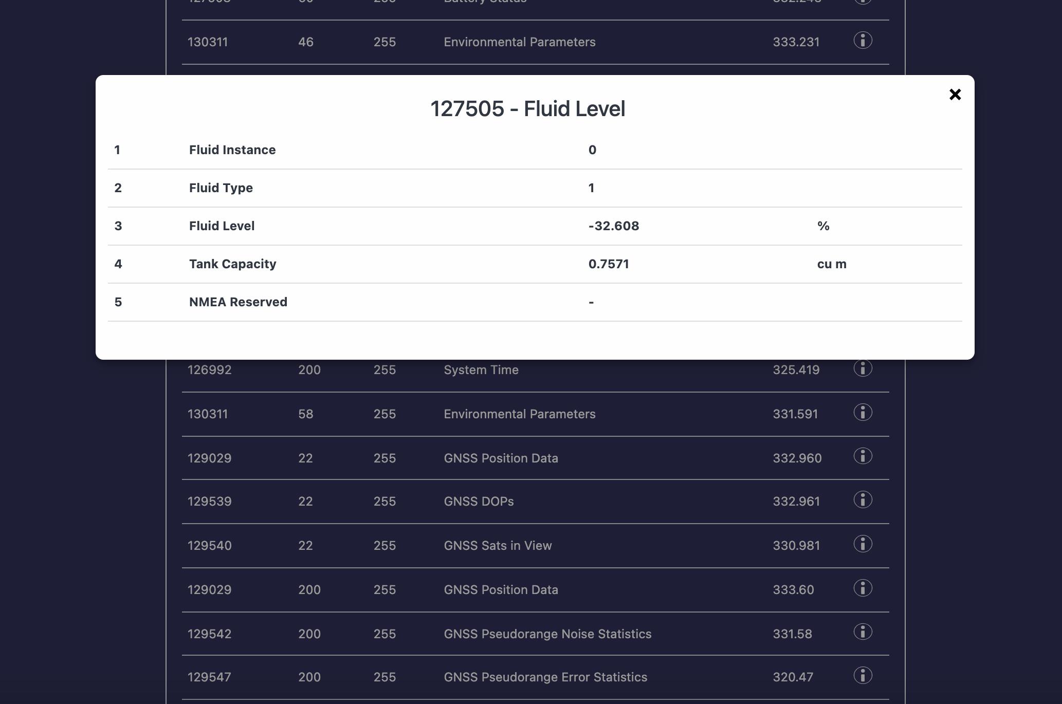

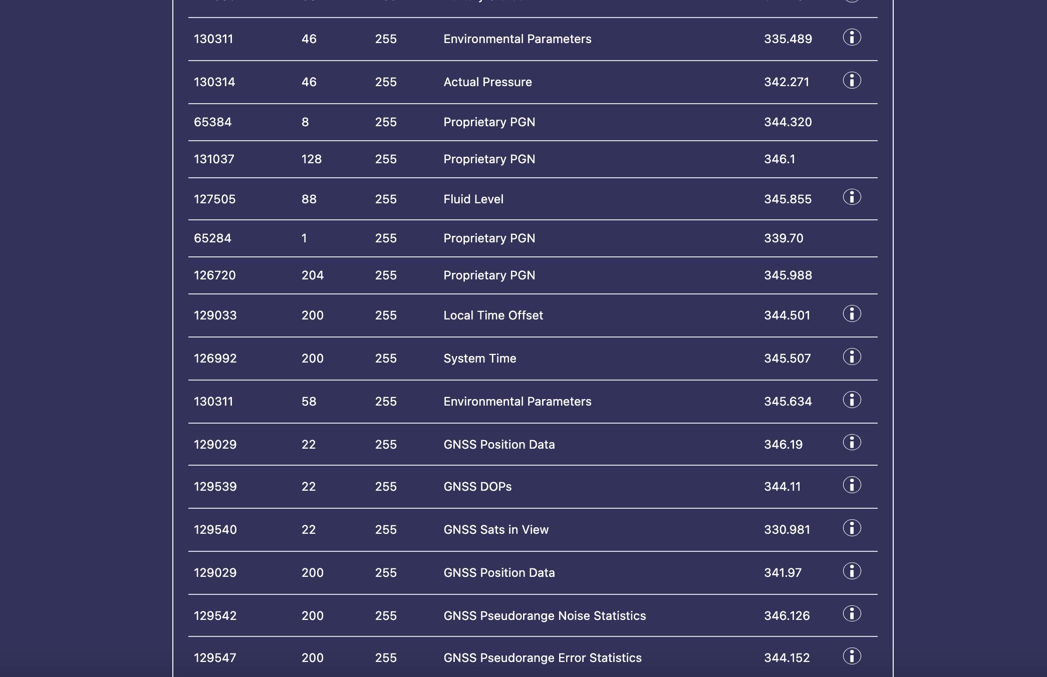
The PGN list shows the PGN number, CAN source of the message, the destination, text description of the PGN, timestamp, and if NAVDoctor knows how to decode the PGN, a clickable information icon that brings up a popup showing the PGN contents.
NAVDoctor’s device and PGN functions aren’t as advanced as tools like Maretron’s N2KAnalyzer. For example, I couldn’t find a way to start at a device on the network and then view and explore all PGNs transmitted by that device. You could look up the CAN ID of a device in the device list, then open the PGN list and search for that CAN ID.
Additionally, the PGN decoding doesn’t seem to be as robust as other tools I’ve used. Most of the decoding is pretty raw. For example, instead of showing what fluid the Fluid Level is set for, it just shows the integer identifier for that type. You can go and look up the fluid types in the PGN definition, but that’s a couple of additional steps.
Network Test Report
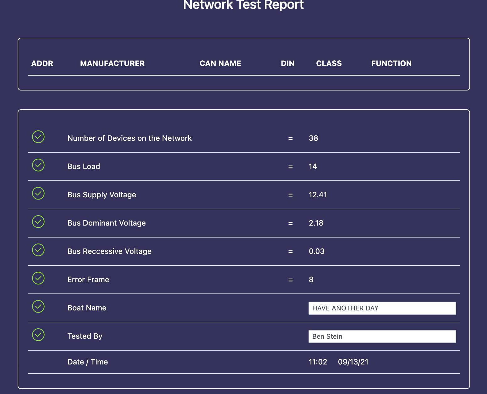
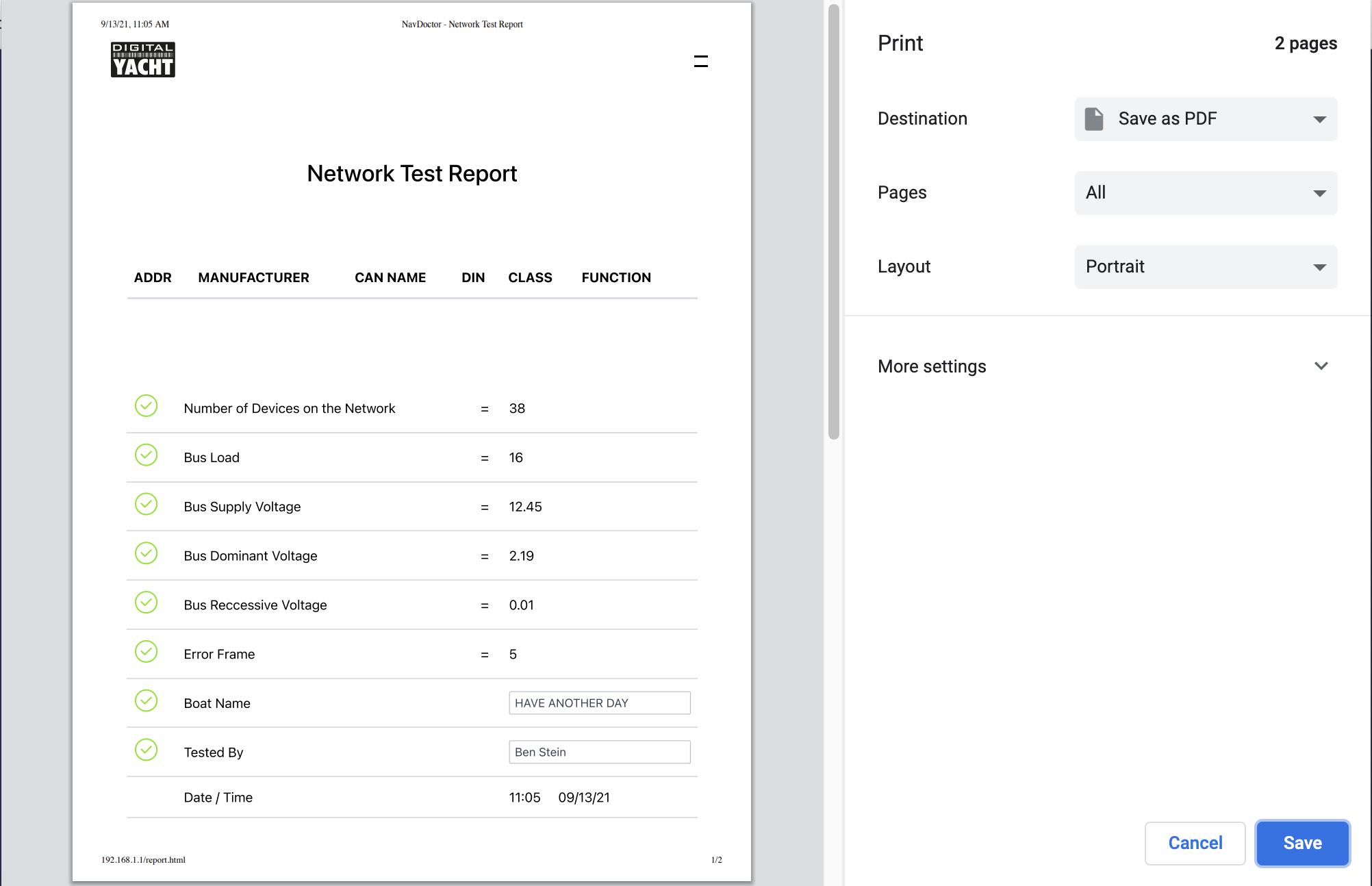
Network Test Reports allow boat builders, installers, and technicians to document the state of the network when they’re done working on a boat’s network. The reports show the basic network configuration when a technician tested including the number of devices, busload, voltages, and error frames.
I can clearly see the value of a report documenting the state of a customer’s network when leaving their boat. I like Digital Yacht’s report so far, but hope they will add more information to the report over time. The more that’s documented in the report, the more useful in understanding and troubleshooting a network.
More helpful help
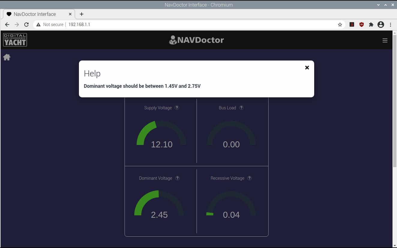
I think Digital Yacht’s biggest opportunity to improve NAVDoctor is by expanding the help information built into the device. As you can see in the screenshots above, the current help screens are quite brief. They don’t expand on that basic information with some troubleshooting. For example, dominant voltage can indicate too many or too few terminators. It would be great if the help explained this and gave a few troubleshooting steps for values outside of the normal range.
I realize that Digital Yacht may be aiming the product towards experienced installers who presumably know what the measurements mean and what out-of-range values suggest. But, I suspect there are plenty of installers who could benefit from this information. Plus, by expanding the help they may also expand the market to boat owners who might not have encountered these situations previously.
Lastly, in the introduction video, Paul Sumpner mentions that NAVDoctor is a close relation to their NAVLink 2 NMEA 2000 to WiFi gateway. With the presence of both an NMEA 2000 interface and WiFi radio, the hardware should be there to allow the NAVDoctor to act as an NMEA 2000 to WiFi bridge. I think it would be a great product enhancement to enable that functionality in the NAVDoctor.
Actisense A2K-TER-U
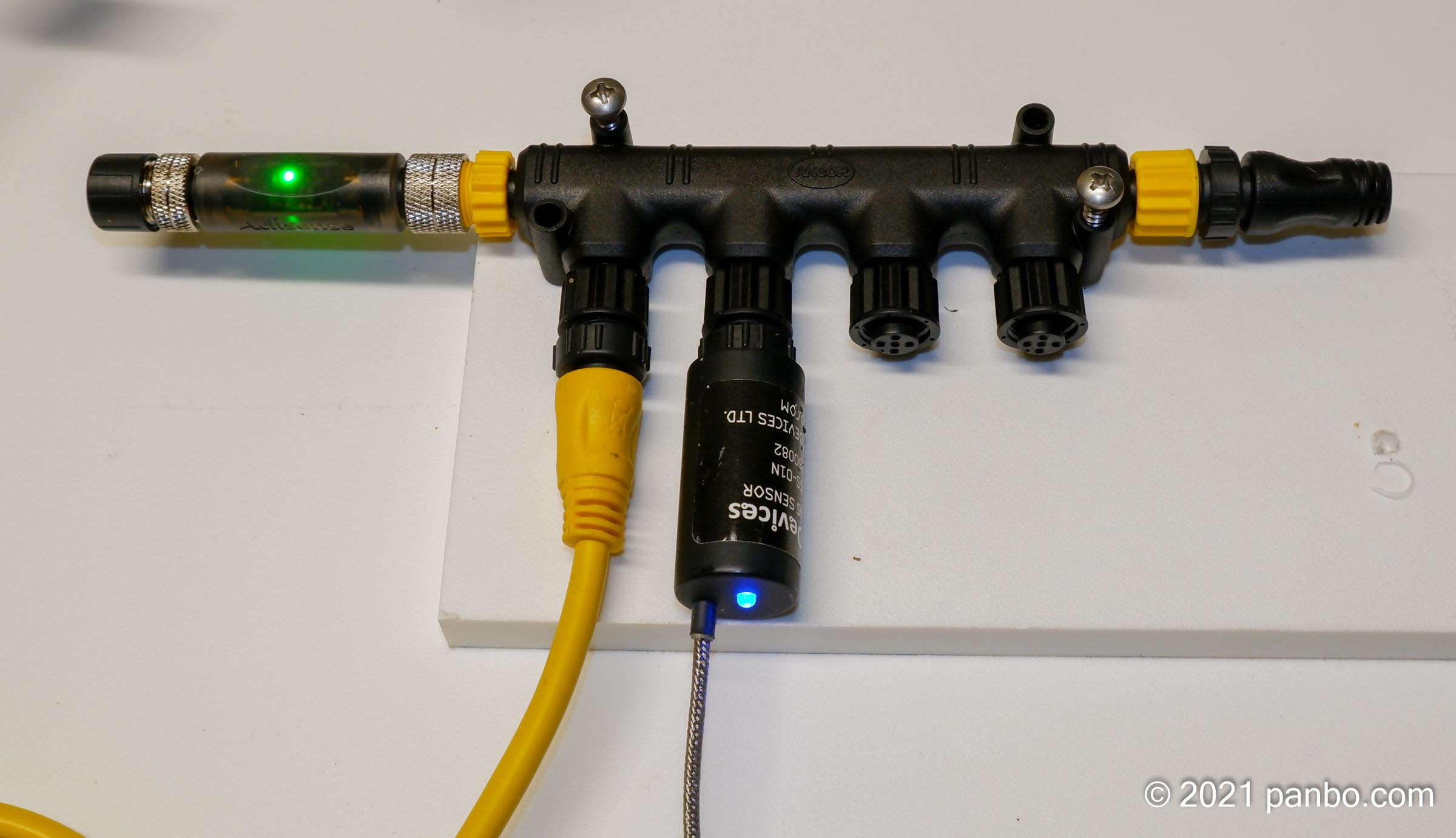
Compared to NAVDoctor, the Actisense A2K-TER-U is a pretty simple device. But, its simplicity is also its greatest value. This handy little terminator can, at a quick glance immediately confirm that a network is powered up and has healthy voltage. The first time I saw one I immediately saw the value it adds and wondered why no one had thought of it before. The A2K-TER-U is an NMEA 2000 terminator with a dual-color LED built-in. The green LED illuminates if the network is powered with voltage greater than the NMEA 2000 spec minimum of 9. If voltage dips below 9 volts the red LED will illuminate.
Additionally, the LED will only light if the polarity of the network is correct. So, at a glance, a green LED on the terminator shows network power with the correct voltage and polarity. It can be a real aid in troubleshooting a network to simply know that if you can find the two terminators, both with green LEDs illuminated, the power of the network is within spec.

The A2K-TER-U has both a male and female connector. It includes caps for both connectors so you can cap the unused connector. But, if you’re using the terminator at the end of a mast connection or similar circumstances, you can use it as a feed-through terminator.
The terminator lists for $40 but is available from online retailers for about $33. A pair of these terminators certainly cost more than traditional terminators. But, an NMEA 2000 network will only ever use two of them. So, I’d say that the diagnostic capabilities, visual confirmation of power, and connection flexibility make it pretty easy to justify spending $66 on a pair.
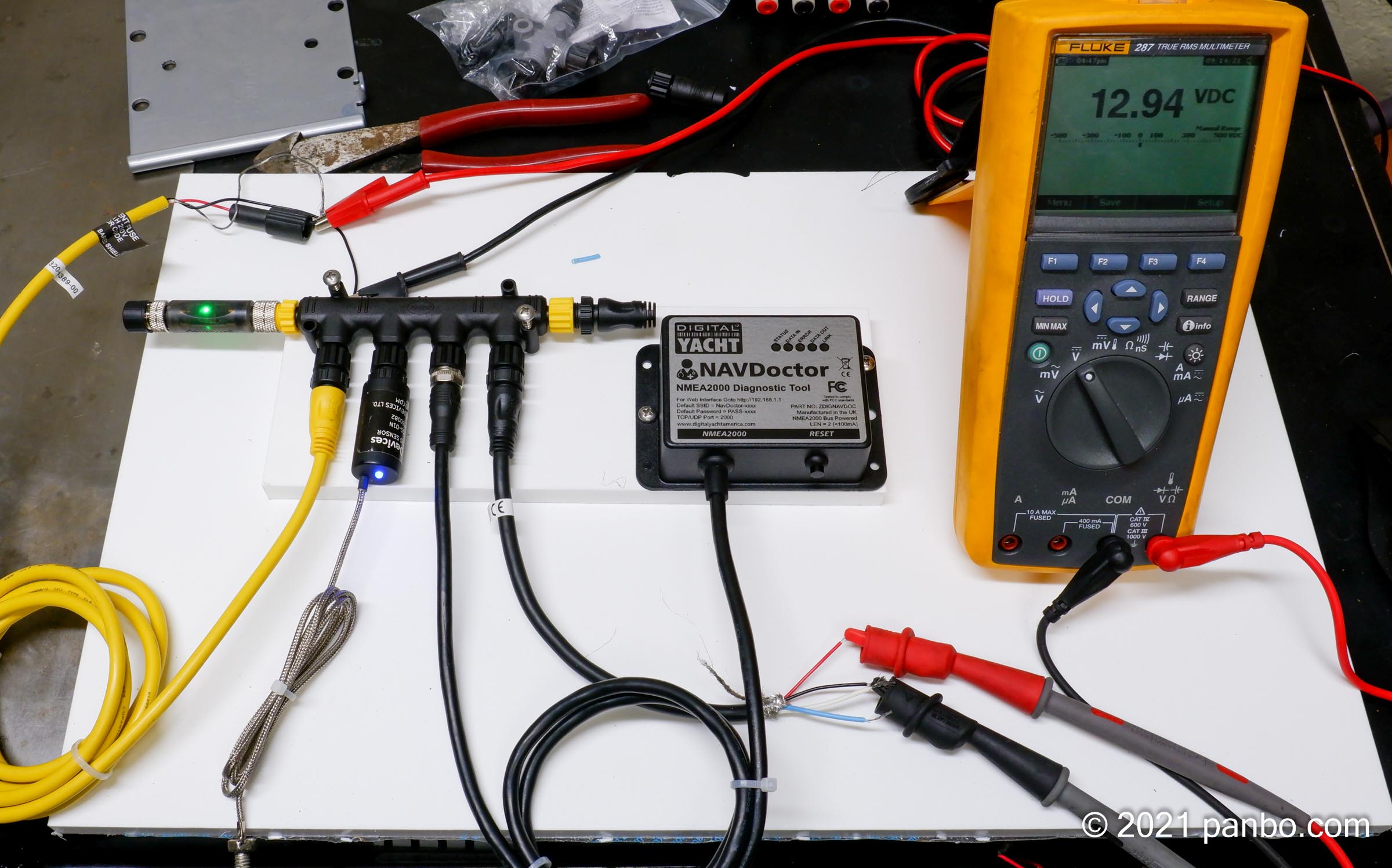
DIY Breakout cable
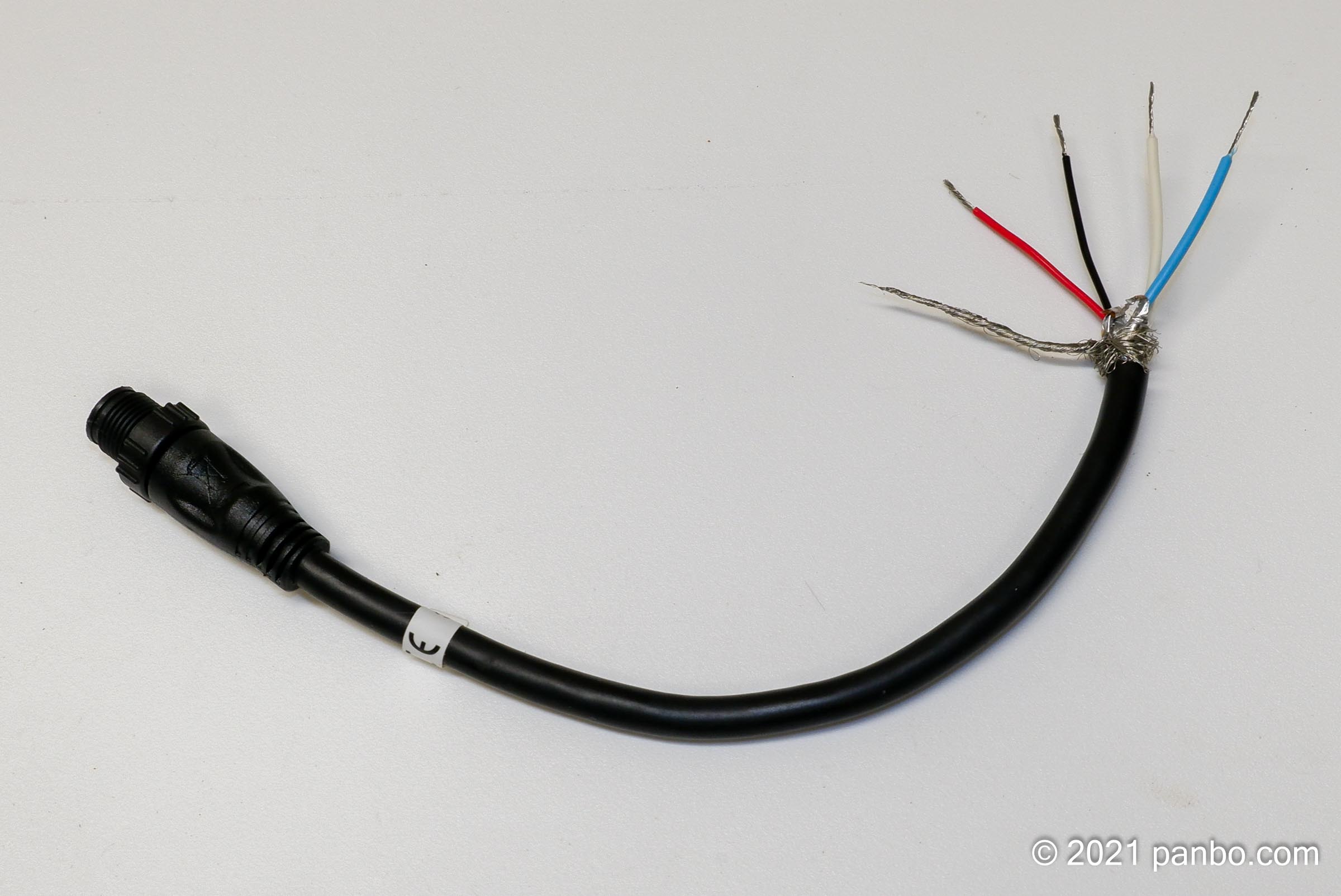
The tools I’ve discussed above derive a lot of their usefulness by measuring basic values on the NMEA 2000 network. You can do the same thing with a multimeter, but you need a way to access the network conductors. It’s possible, but not easy or reliable, to put the probes of a multimeter into a male NMEA 2000 connector. But, if you’re not careful you can pretty easily short the pins. It’s easier to work with a DIY breakout cable. That’s a fancy name for an NMEA 2000 cable with one end cut off and the conductors stripped back.
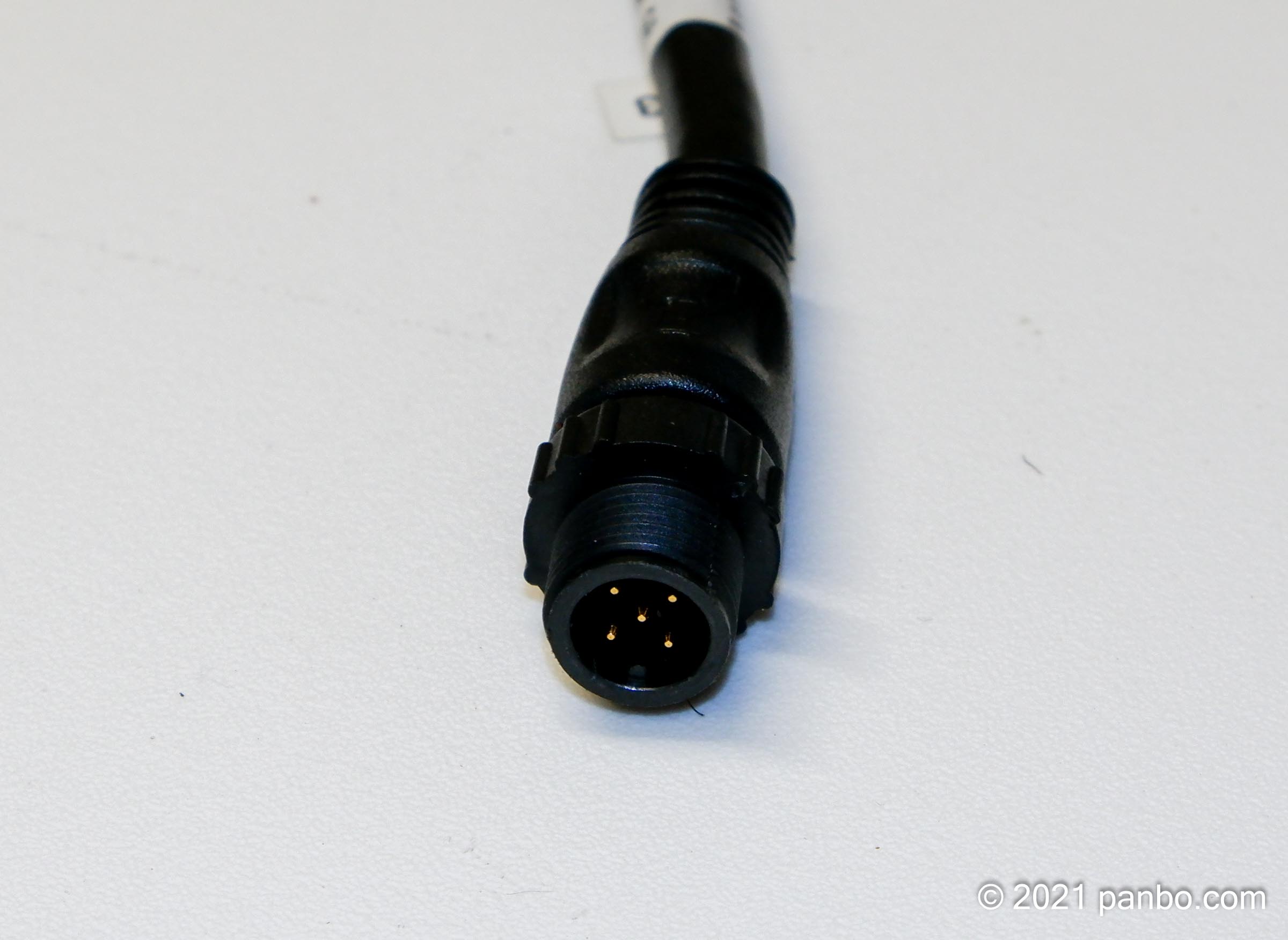
I start with the male end of the cable because it will connect to drop ports on tee-connectors as well as one of the backbone ports. It’s easy to do the same with the other end of the cable if you need to connect to male ports. Once the wires are stripped you have access to the signal and power wires of the network.
| Color | Name | Usage |
|---|---|---|
| White | Net-H | Signal (CAN Hi) |
| Blue | Net-L | Signal (Can Lo) |
| Bare | Shield | Drain |
| Black | Net-C | Ground (12-volt -) |
| Red | Net-S | Power (12-volt +) |

The DIY cable can be easily used to check network voltage and resistance. By connecting to the black and red wires you can check voltage. The NMEA 2000 spec calls for no more than 1.5 volts of power drop between any two devices. If you suspect your network is experiencing voltage drop over its length, you can connect the test cable in multiple locations along the network. I find Maretron’s NMEA 2000 Network Installation Guide a very useful reference for network design and installation.
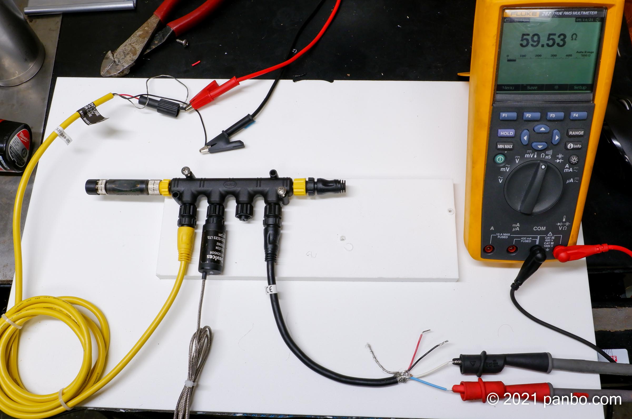
Proper termination can also be easily tested with a breakout cable. By setting your meter for resistance and connecting the probes to the Net-H (white) and Net-L (blue) wires you can read the resistance. You will need to remove power from the network for your meter to be able to measure resistance. With two 120-ohm resistors on the network, you should measure around 60-ohms of resistance.
Access to the conductors of your NMEA 2000 network opens up other possibilities. In fact, I’ve ordered a really cheap ($41.00) oscilloscope from Amazon. I’m curious to see what else about the networks operations I can learn with the oscilloscope.
Final thoughts
NMEA 2000 networks mostly just work. But, the tools I’ve discussed can help you ensure your network remains healthy and that you’re setting yourself up for sucess. My network on Have Another Day usually has around 40 devices on it and I’ve learned that paying attention to fundamentals helps keep everything working smoothly. If you have tips or tricks that you’ve found work well for troubleshooting your networks, I’d love to hear them.


Another great article. A couple of Led terminators and a breakout NMEA 2000 breakout cable is a good start for a toolkit for helping others. I also like info on CanBus networks. It’s very common in cars, boats and many automation circuits.
Also interested in further information on using the oscilloscope to further diagnose things. Never receive any training on what they can do!
When using an oscilloscope for NMEA 2000 diagnosis I’m using a differential probe to connect to the bus and I’m looking at the eye diagram.
https://www.testandmeasurementtips.com/basics-eye-diagrams/
Good article, Ben. In addition to the “…. first two thoughts are power and termination”, I would also add any field-attachable connectors in the system. As I’m sure you know, these can be really challenging to assemble, and any extra resistance or an open circuit is sure to cause trouble. I was able to borrow one of the Maretron N2K meters last time I had to trouble shoot a problem, and with that and a breakout cable it was pretty easy to find the culprit.
Grant, great point about the field installables.
I don’t understand what’s the problem with field attachable connectors. I’ve used them for more than 10 years, very easy to install and reliable.
Well I can only speak for myself, and the issues I’ve discovered while troubleshooting them. I’m familiar with the Mareton product – perhaps there are other’s that are easier, but I’ve not met anyone who would describe them as “very easy” to install. In particular, if you don’t add a section of heat-shrink to the bare conductor (“recommended” by Maretron but not included in the kit) you’re almost guaranteed to have problems.
I have mostly used the Maretron connectors. For an EE with 30 years experience in product development it’s very easy to install these;-)
OK, if you say so. Apparently my skills need sharpening. For me, I’ll continue to stick with factory-installed cable terminations, and eliminate any possibility of a bad connection….
We use these connectors, both Micro and Mini in a product I’ve been involved in developing. I’ve also used them in my boat. It’s not originally Maretron connectors, they are just marketing these. it’s Molex Brad Mini and Micro Change connectors, developed for DeviceNet industrial networks. It’s the easiest connector I terminate, all other connectors I terminate for lab work or prototyping are more challenging, most of them much more challenging to terminate involving soldering or crimping.
Exactly, it’s a standard M12 connector that you can get from Digi-key for about 1/2 the price. I keep several handy and have not had any problems with them, but then I’ve done thousands of telecom and audio terminations over the years.
This video on Youtube has also some nice throubleshooting tips for a CANBUS (applies to NMEA2000 too, as it is a CANBUS):
Name: CAN Bus Properties and Troubleshooting
Link: https://youtu.be/ulcKnrPmJqM
Maybe someone can explain what it means if I tested the resistance with power off and my multimeter showed 116 ohms. Does that mean I am missing a termination at one end of the backbone? Thanks.
For sure you miss one termination on the bus:
– The terminater itself can be broken (I had this with a brand new one, it dus not have to effect the canbus with only a few devices, so you will only notice this when measuring it with a multimeter). Replaced the terminator itself, easy fix.
– The backbone is not connected properly. Something lose?
– Broken wire in the backbone.
A missing or broken terminator would be the most likely scenario if your bus resistance is too high.
For *most* simple networks (eg: any average pleasure boat) you might not ever have any problems, though if the remaining terminator failed, then you might start having a lot of collisions on the network, or other problems with corrupt data and signal integrity.