
Victron NG Smart LiFePO4 batteries, ultimate power flexibility
If you made a list of all the features you require and prefer in your boat’s batteries, I would bet that Victron’s NG Smart batteries would check just about every item on your list. In a field where it sometimes feels like we are all field testing products, Victron’s batteries, BMSs, and software evidence maturity and integration most other manufacturers can only dream of achieving. About the harshest thing I can say about Smart NG batteries is that they’re more expensive than some of the other batteries out there. But, stick with me and we’ll take a careful look at what you get for that extra expense.
Let’s start with an acknowledgement of something that might seem obvious. Victron has an advantage when it comes to making batteries integrated with the Victron ecosystem. Since they created the ecosystem, and can modify it to best work with their own products, they have a significant leg up in integrating with it. Many of the batteries I test claim Victron communications abilities. Over time, my testing has shown that the reality is that some batteries communicate better than others. Not surprisingly, Victron’s batteries offer a level of communication and integration with their Venus OS and GX devices that no other battery can touch.
Next generation hardware
The NG in Smart NG stands for next generation. As the name implies, NG batteries and BMSs succeed Victron’s Smart LiFePO4 batteries. NG brings several major improvements including more compact batteries, additional data and alarming from the batteries, automatic battery firmware updates performed by the BMS, reduced self discharge rates, dust and moisture resistance moves from IP22 to IP65, better battery mounting options, more batteries supported per BMS, and perhaps most importantly, the rollout of NG batteries brought the ability to combine multiple BMSs and their batteries into a single virtual battery.
Next generation batteries
NG batteries are available in 12, 24, and — for the first time — 48 volt nominal configurations. 12 volt batteries range from a 1,280 watt-hour, 100 amp-hour option to the 3,840 watt-hour, 300 amp-hour model. 24-volt batteries start at 2,560 watt-hours and 100 amp-hours and range up to 7,680 watt-hours from the 300 amp-hour model. Currently Victron only offers one 48-volt nominal battery at 5,120 watt-hours or 100 amp-hours.
All Smart NG batteries are rated for 2,500 cycles at 80-percent depth of discharge and 5,000 cycles at 50-percent. Victron rates all the batteries for 1C continuous charge and discharge and, for most of the line, 2C for 10 seconds of pulse charge or discharge current. The 12v/150ah, 12v/300ah, and 24v/300ah support 1.5C pulse charging. With 12 and 24 volt batteries, each BMS supports a maximum of 50 batteries connected. With 48 volt batteries, the per BMS limit drops to 25. Each GX system supports up to 5 NG BMSs. If I understand the limits correctly, that means a single GX instance could support up to 250 batteries and 1.9 megawatts of storage capacity. I don’t foresee marine or mobile installations pushing those limits.
Next generation BMSs
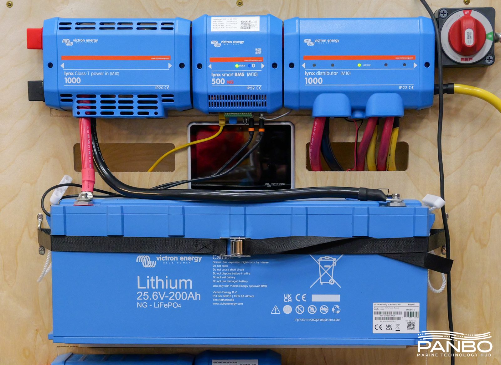
Victron offers a total of four NG BMSs. From smallest to largest, the lineup includes the SmallBMS NG, VE.Bus BMS NG, Lynx Smart BMS NG 500 A and Lynx Smart BMS NG 1000 A. The smaller two, out of the box, won’t meet ABYC E-13’s requirements for a BMS controlled disconnect device. However, they do have allow to charge and allow to discharge terminals that could be used to control an external relay or contactor to meet the requirement. In contrast, the Lynx Smart BMS NGs feature built in contactors to meet all ABYC requirements and enable the safest possible installations. The 500 amp Lynx NG BMS supports 500 amps continuously and surge current of up to 600 amps for five minutes. The 1000 amp model supports 1,000 amps continously and up to 1,200 amps for five minutes.
Both sizes of Lynx Smart NG BMSs feature a pre-charge resistor. As the name implies, they pre-charge capacitive loads like inverters to minimize high-current inrush when the contactor closes. The pre-charge functionality is automatic and likely occurs without any user awareness. Additionally, all the NG BMSs utilize allow to charge and allow to discharge contacts. These contacts change state when the BMS determines the battery should no longer be charged or discharged. The contacts are not needed for charge and discharge devices that communicate via a GX device. However, the contacts enable control of other non-communicating sources including older Orions and non-Victron branded equipment.
Victron batteries come at a premium compared to many of the value oriented batteries in the market. Each battery bank needs a BMS. The Lynx Smart BMS 500 NG has a minimum retail price (MRP) of $803.25 and the 1,000 amp model has an MRP of $1,071. NG batteries range widely in price based on capacity. At the lower end, the 100 amp hour, 12 volt battery has a $973.25 MRP. On the high end of capacity, the 300 amp hour, 24 volt battery weighs in with a $3,933.80 MRP.
Lets compare to some other batteries out there:
| Description | Battery cost | BMS/Hub Cost | Watt-hour capacity | $/watt-hour |
| BattleBorn 100ah 12v Smart | $899 | $149 | 1,280 | $ 0.82 |
| BattleBorn 270ah 12v Smart | $2,299 | $149 | 3,456 | $ 0.71 |
| Epoch 460ah V2 Elite 12v | $2,199 | $0 | 5,888 | $ 0.37 |
| Epoch Essentials 105ah, 12v | $499 | $0 | 1,344 | $ 0.37 |
| Epoch Essentials 460ah, 12v | $1,499 | $0 | 5,888 | $ 0.25 |
| Lithionics 630ah 12v | $8,923.95 | $0 | 8,064 | $ 1.11 |
| LiTime 280ah 12v Smart | $609.99 | $0 | 3,584 | $ 0.17 |
| Mastervolt Mli 12/6000 | $6,088.26 | $0 | 6,000 | $ 1.01 |
| Victron 1x100ah 12v | $973.25 | $803.25 | 1,280 | $ 1.39 |
| Victron 2x200ah 12v | $2,966.5 | $803.25 | 5,120 | $ 0.74 |
| Victron 4x100ah 12v | $3,893 | $803.25 | 5,120 | $ 0.92 |
| Victron 4x300ah 24v | $15,735.2 | $803.25 | 30,720 | $ 0.54 |
As you can see, Victron isn’t going to be the least expensive option out there. In fact, large lower cost batteries, like the Epoch Essentials and LiTime batteries, are dramatically cheaper. However, no other battery in this list delivers the features and capabilities of the NG batteries. In fact, although it makes sense to evaluate the options, comparing these batteries to a simple drop-in battery without Victron comms is a stretch.
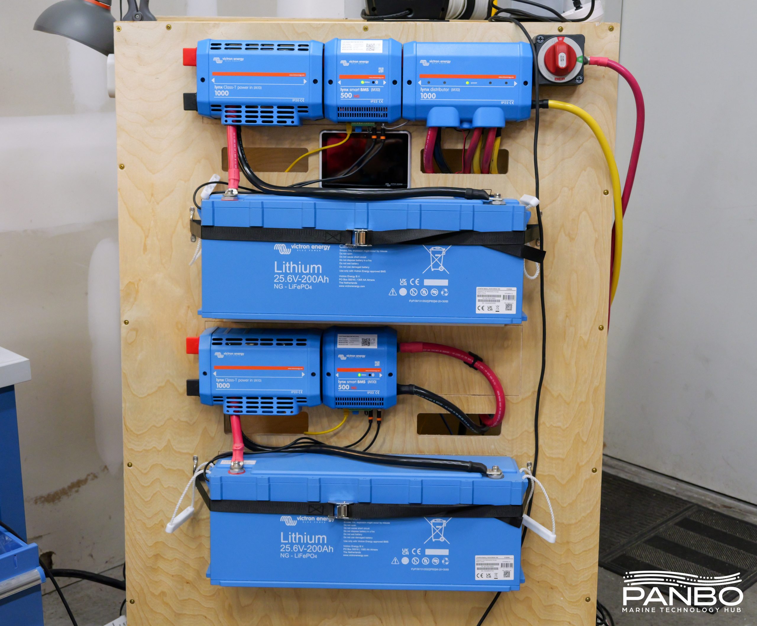
Paralleling Lynx BMSs to create virtual batteries
With the introduction of the NG series of batteries, Victron added the ability to parallel BMSs and create virtual batteries. Virtual batteries combine multiple strings or banks of batteries — with each bank controlled by its own Lynx BMS — into one logical battery. The virtual battery represents the total of all paralleled banks.
During normal operations, the main difference with virtual batteries is the rolled up reporting displayed for the virtual battery. Virtual batteries allow mixing of both Lynx Smart BMSs and Lynx Smart NG BMSs. However, Smart batteries need to be behind a Smart BMS and NG batteries behind a Smart NG BMS. Additionally, you can only combine BMSs with the same current handling ratings.
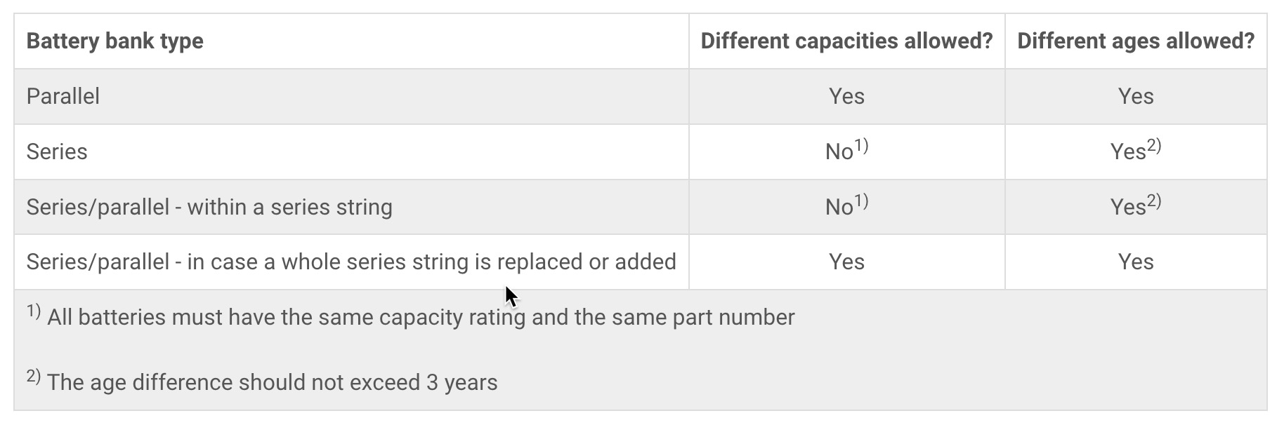
As the table above shows, the system supports numerous options for the individual strings of batteries behind each BMS. Additionally, there is no requirement that the total capacity behind each BMS be balanced. So, you could parallel a 24v, 1,200 amp hour string behind one BMS with a 24v, 200 amp hour string behind another. As probably goes without saying, voltage must match across all BMSs.
At first glance, you might be thinking that parallel BMSs and virtual batteries is just a reporting nicety and doesn’t change functionality. During normal operations, there’s some truth to that. But, when things go wrong or get complex, parallel batteries really shine. Victron has written extensive logic to ensure safe combining and separating of BMSs and their batteries. If a BMS and its associated batteries disconnect from the DC system — whether automatically because of a fault or manually by operator intervention — the system manages the disconnection and reconnection. When a bank is removed, the system reduces the ratings on the virtual battery to reflect the new capacity. When the removed bank is ready to rejoin, it waits until voltages are safe to recombine them.
Dynamic DVCC
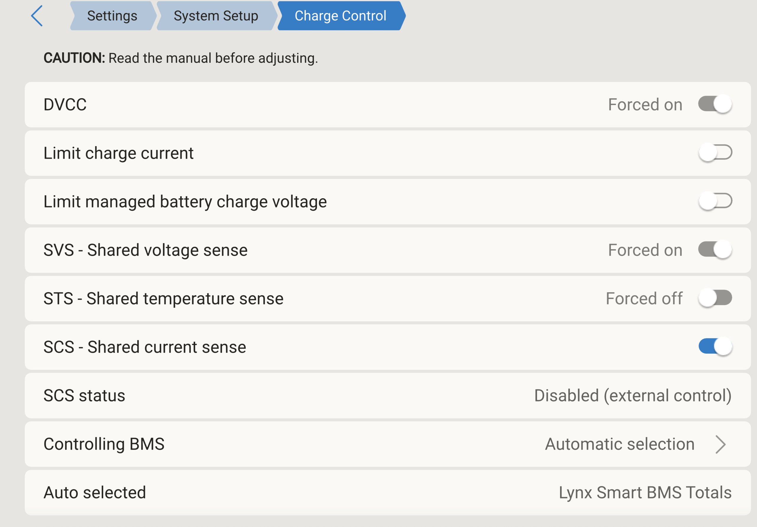
Victron’s DVCC, or distributed voltage and current control, allows battery BMSs to communicate with other components on the GX network. Via this mechanism, the batteries indicate desired charge voltage as well as charge and discharge current limits. DVCC becomes an integral component of parallel batteries.

The table above shows how various battery parameters from individual BMSs combine to set the values of the virtual battery. For DVCC, the lowest charge voltage limit from individual BMSs is communicated to charge sources. The virtual battery sums charge and discharge current limits from all connected and online BMSs.
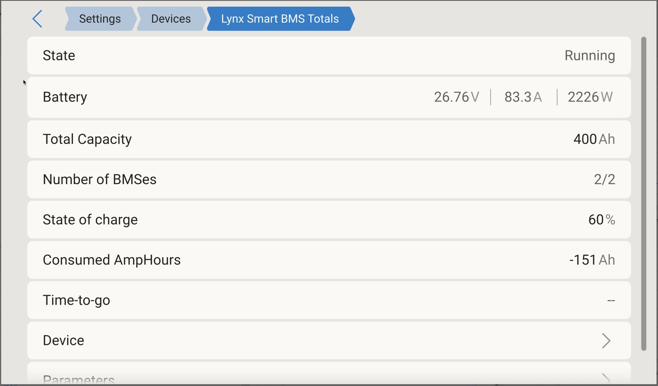
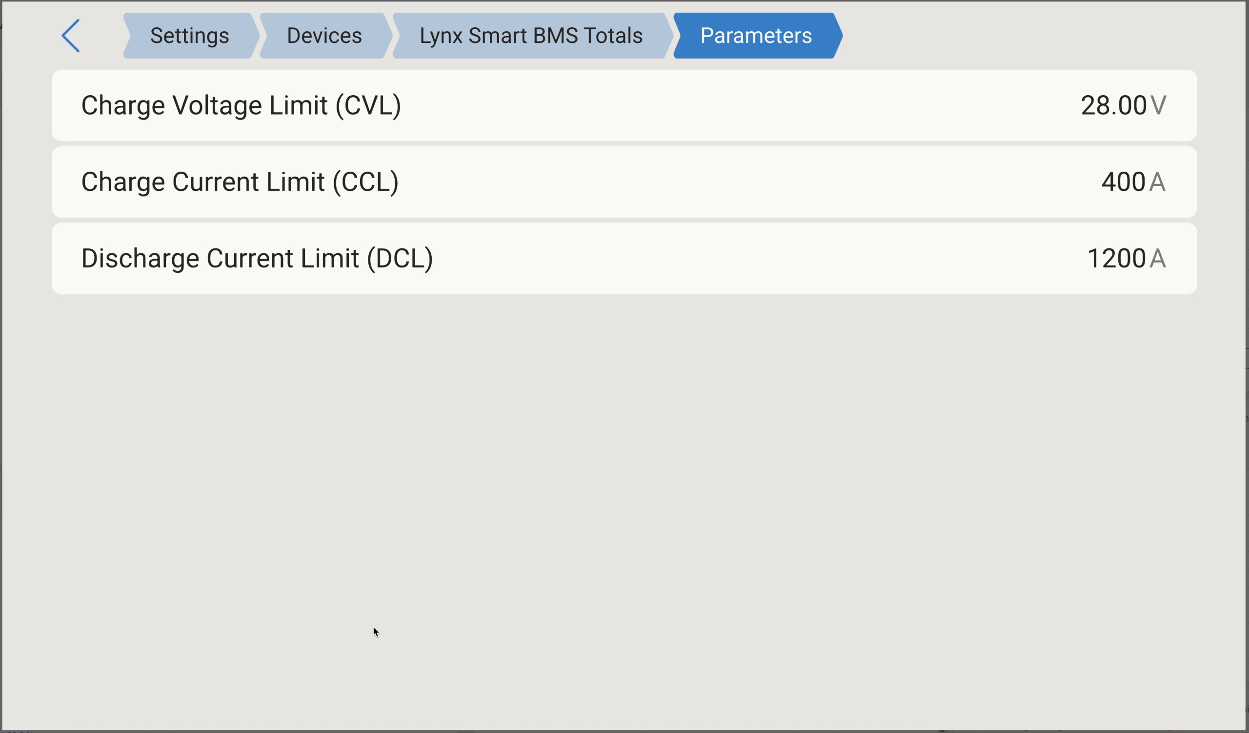
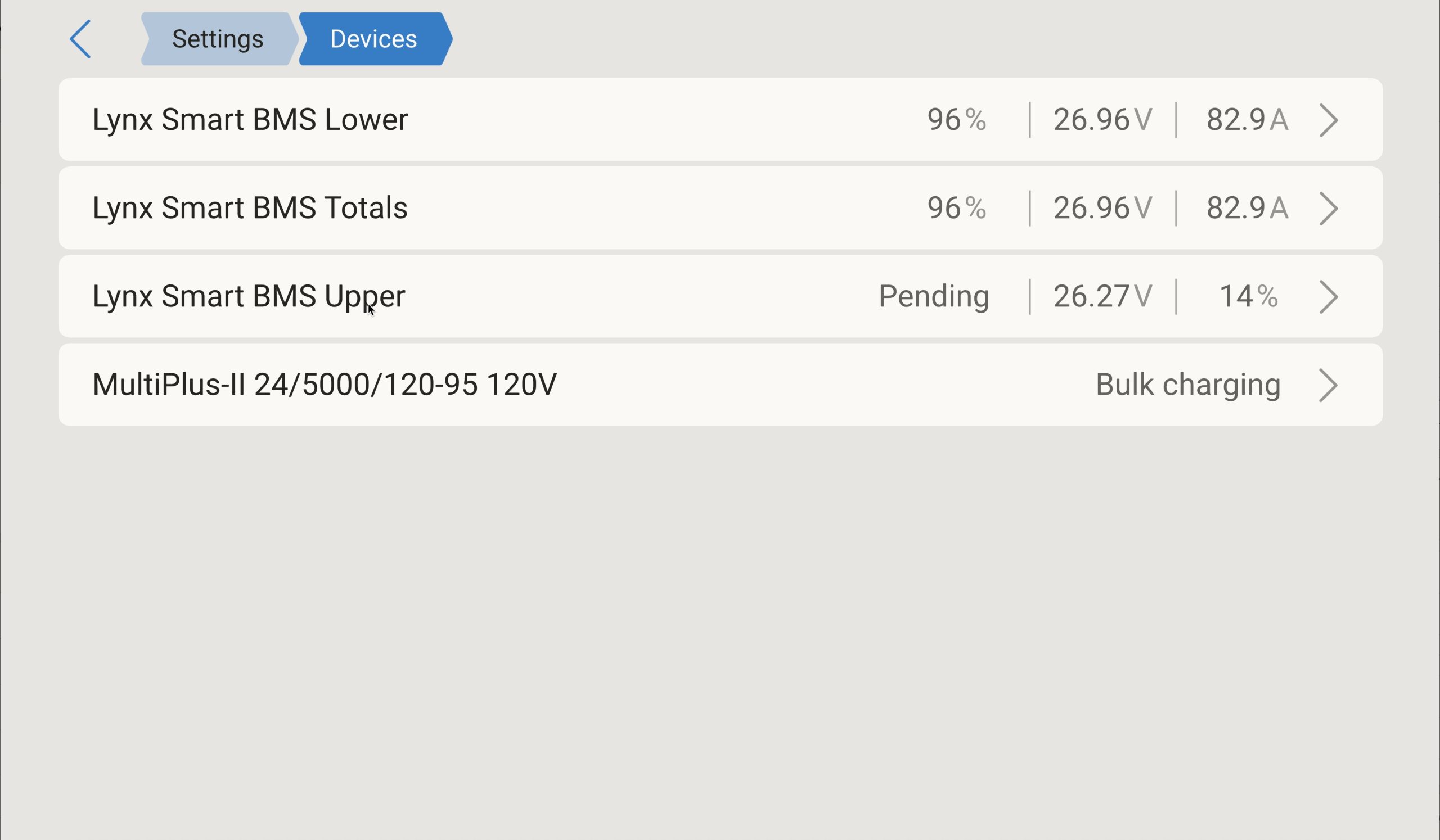
In my test system, with one battery behind each BMS, DVCC sets CCL to 200 amps per BMS and DCL to 600 amps per BMS. The BMSs command a CVL of 3.5 volts per cell or 28 volts for a 24 volt nominal system.

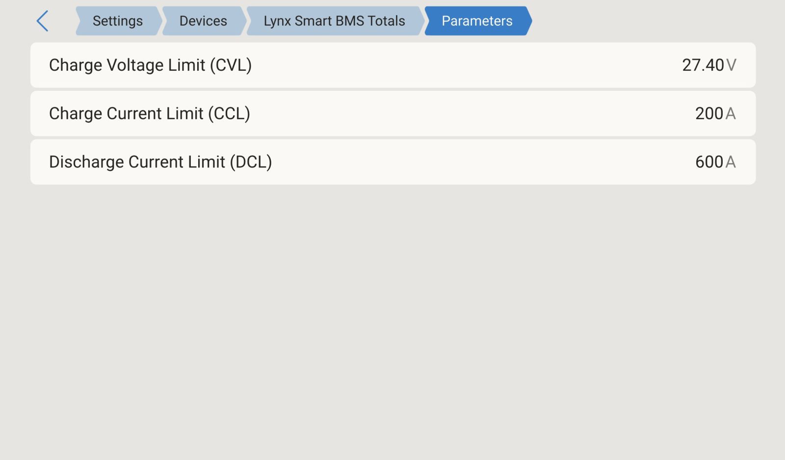
The two images above show VRM’s status with one of the two physical batteries removed from the virtual battery. Essentially, all values reduce by 50 percent but operations continue normally. The online battery is at 100 percent SOC in the second screenshot so the CVL calls for a float value. Although I did all my testing with two BMSs and one battery behind each BMS, this same system could scale up to five BMSs with 50 batteries behind each BMS. If resilience is a priority, like in the case of an offshore cruising boat, size the sytstem to cope with the loss of a BMS and associated batteries.
Performance

This is normally where I talk about how the various components of the batteries hold up to extreme load. I’m pleased to say this section is going to be rather boring. The only time I’ve induced anything even slightly interesting was with a loose negative connection to one of the batteries. As soon as I placed a heavy load on the system, I got an over-temperature warning. I quickly found the loose terminal, tightened it up and all returned to normal. My testing included over 200 amps load on a single BMS and attached single 200 amp hour, 24 volt battery. Although the BMS is rated for 500 amps continuous, the battery is only rated for 200 amps continuous and 400 amps for up to 10 seconds. However, I’ve never seen any issues from the batteries, even when I’ve pushed them past their ratings.
Connecting multiple BMSs in parallel
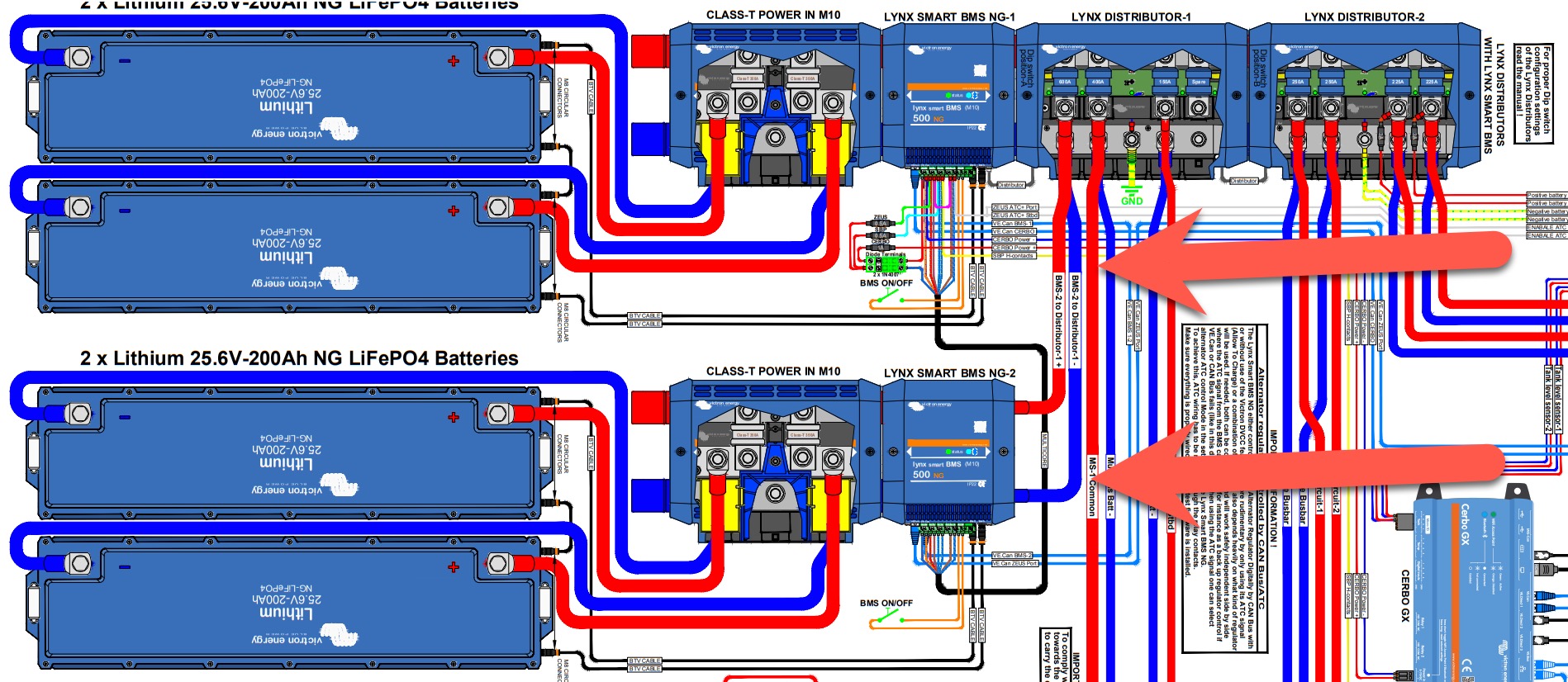
One of the challenges of tying in multiple BMSs is the location of the tie. Victron’s Lynx system bolts together and is designed to have a single BMS in the middle with battery connections on the left and loads on the right. But, what do you do when you have two BMS? You can’t chain them together side by side. So, effectively, you need to have two separate Lynx busses and tie them together. The snippet above comes from one of Victron’s reference design drawings. In it, you can see — as I’ve pointed out with the arrows — that Victron’s reccommended approach is to cable the ouput lugs of the second BMS to the distributor side of the first one.
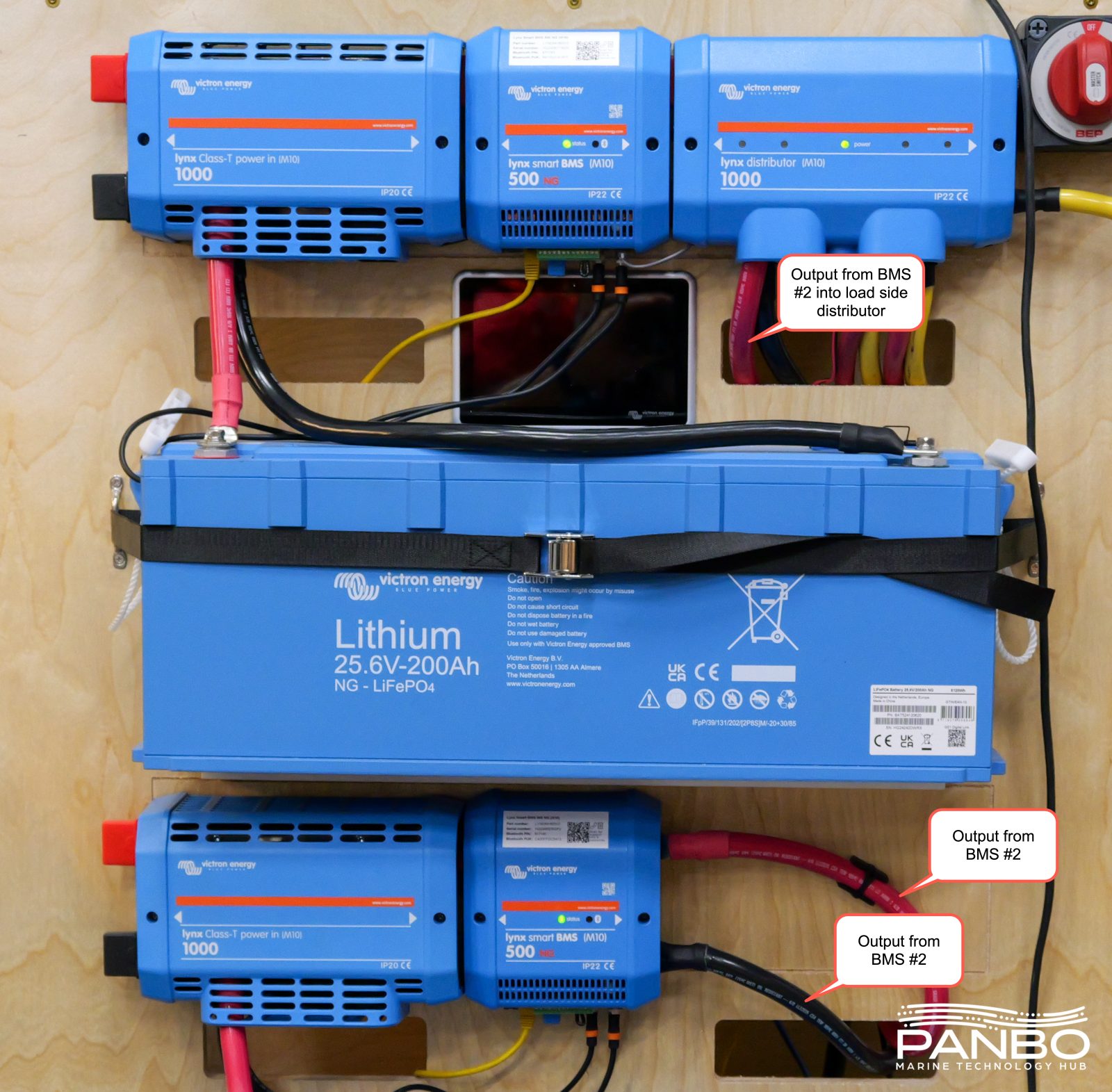
In building my test setup, I followed the reference drawing’s suggestion and wired up the output of BMS #2 to the distributor attached to the output of BMS #1. The approach works just fine but, as you might expect, results in unequal charge and discharge rates. This makes perfect sense since the cabling paths to the two BMSs and batteries are of different lengths.
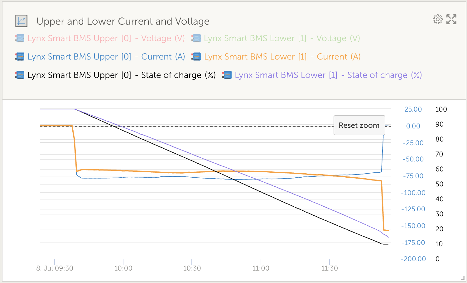
The chart above illustrates the behavior I’ve observed running the system with differing wiring resistance. The blue line is the upper BMS with its shorter wiring run and hence lower resistance. The orange line shows the lower BMS with greater resistance from its longer wiring run. Lastly, the black and purple lines represent state of charge of each battery. The discharge test began with both batteries at 100-percent SOC. As soon as the load hits, we see the upper BMS handle more load. Eventually, the lower BMS begins handling more of the load as the upper battery’s voltage sags as the SOC declines.
About one hour and 45 minutes into the load, the lower battery surpasses the upper and supplies the majority of the load. A few minutes after that, the upper battery hits the 10-percent SOC and the BMS takes over opening the contactor. Now, the lower battery and BMS handle all of the load until that battery also reaches 10-percent SOC and all batteries are offline.
At first, the potential imbalance felt problematic. However, the more I’ve reflected on it, the less trouble I see from it. In testing, I’ve seen SOC drift pretty far apart but it always comes back together during recharge. I’ve tried to force SOC further apart with some partial charge cycles but still haven’t seen any troubles. The more I’ve worked with it, the more I think it may actually provide design flexibility. With all of the management tools for multiple banks, a system designer is now free to utilize multiple battery banks throughout the boat. The system will manage itself and maintain safe operations even as SOC potentially drifts during normal operations.
If this imbalance is problematic, there is a relatively easy solution. Rather than connecting using a distributor connected directly to one BMS, the distributor could be remote to both BMS. Then, equal length wires can be employed to connect both BMSs to the distribtor.
Managing BMS reconnection
In allowing multiple BMSs’ output to be combined, Victron also has to manage the combination and separation of the batteries to ensure safety. If the batteries are combined with too large of a voltage delta, there is a potential to create unsafe conditions. If the voltage delta is too large, very large amounts of current may flow between the batteries. This energy flow could exceed the current handling capabilities of numerous components in the system.
Victron ensures this doesn’t happen by not allowing the BMSs to combine unless their voltages are close enough to ensure safety. It appears Victron has determined the safe delta is a little under one volt. In my experimentation, I’ve created larger deltas and watched the system wait in a pending state for as long as is needed to combine batteries safely. It’s worth noting that it’s possible for a battery to remain pending for a very long time, potentially many hours, if the batteries don’t get close enough in voltage.
Tearing it all apart
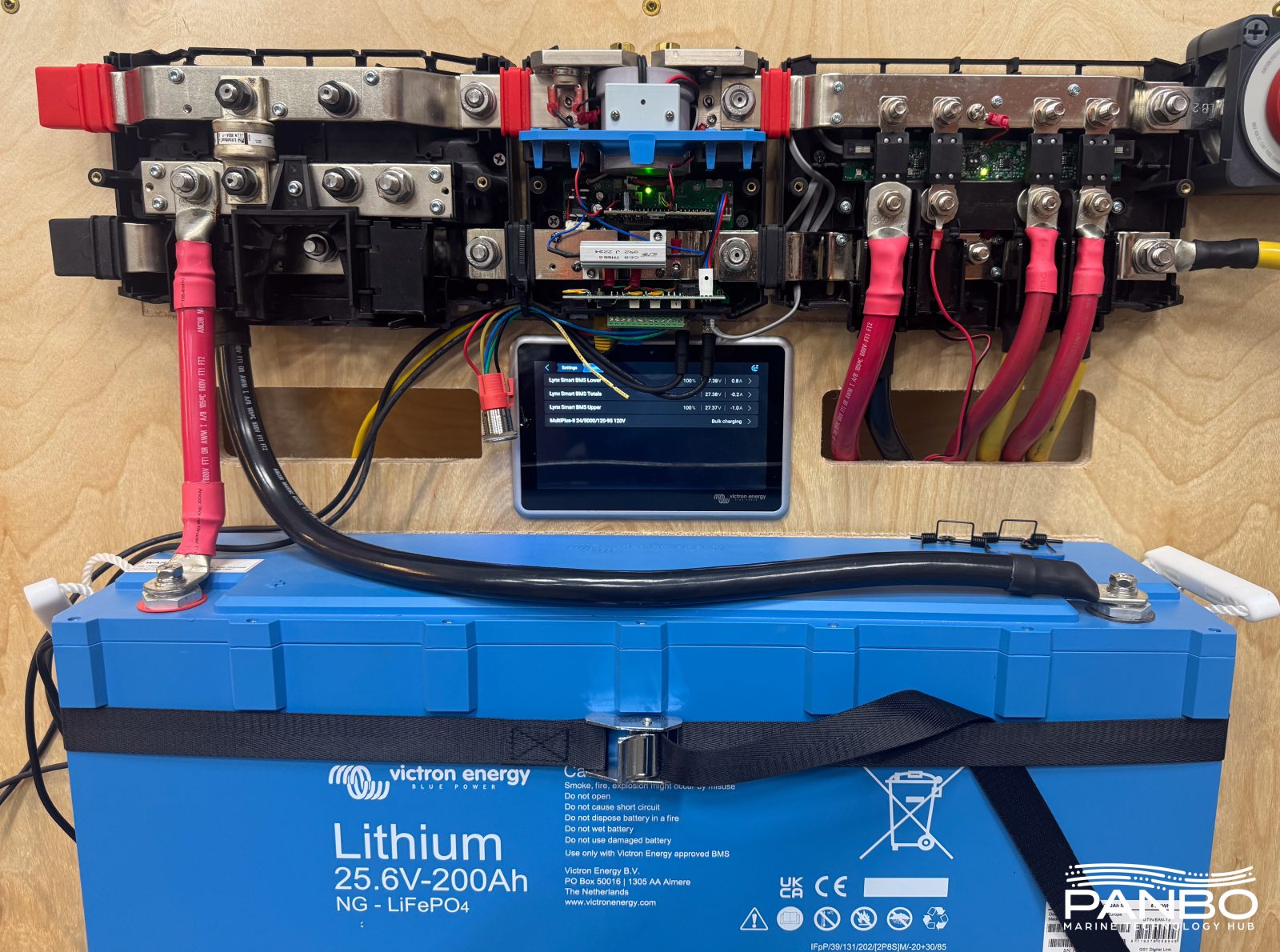
Because Victron uses an external BMS, the battery teardown happens in phases. The first phase simply involves taking the covers off the Lynx components. With the cover off, much of the BMS’ innards are easily on display.
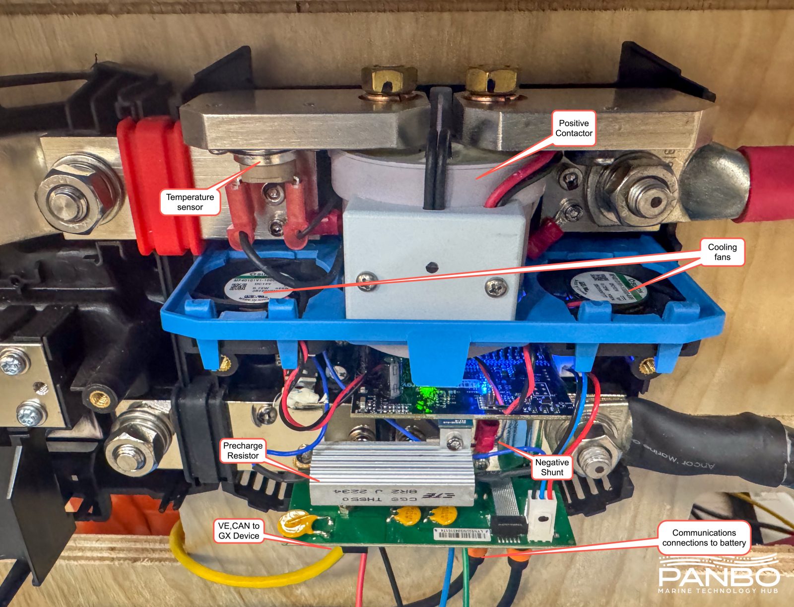
In some respects, contactor based BMSs are simpler. There aren’t rows of MOSFETs for charge and discharge control. Instead, there’s a single, very large contactor in the positive current path. On the 500 amp BMSs I have, the contactor handles 500 amps continuously and 600 amps for up to five minutes. Victron uses a temperature sensor on the positive bus bar to ensure temperatures stay within a safe range. The negative bus bar is actually a shunt with calibrated resistance across it. There are two small cooling fans that I’m yet to hear run, even when pushing pretty large loads.
Opening the batteries is easy, except for the aluminum nuts used to secure the positive and negative terminals into the case. I think the thread must deform when they’re tightened to the posts. I had to really haul on them to get them off and wasn’t able to rethread them back on. In some of the closes-ups, you will see the damage to the thread on the posts.
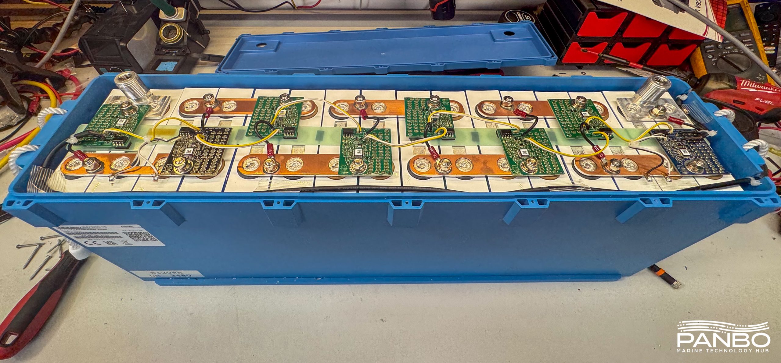
Once inside, the batteries are pretty simple. There are a total of 16 cells in a 2p8s arrangement. Each cell is 100 amp hours at 3.2 volts nominal. Each cell two-parallel cell pair has a cell management module connected. From what I can tell, the module manages balancing and reports on cell voltage and temperature.
With the NG series, Victron moved from analog communications between BMS and battery to digital. Cabling remains the same, so previous battery to BMS extensions can still be used. Digital communications enables the exchange of more parameters over the same 3 wire connection.
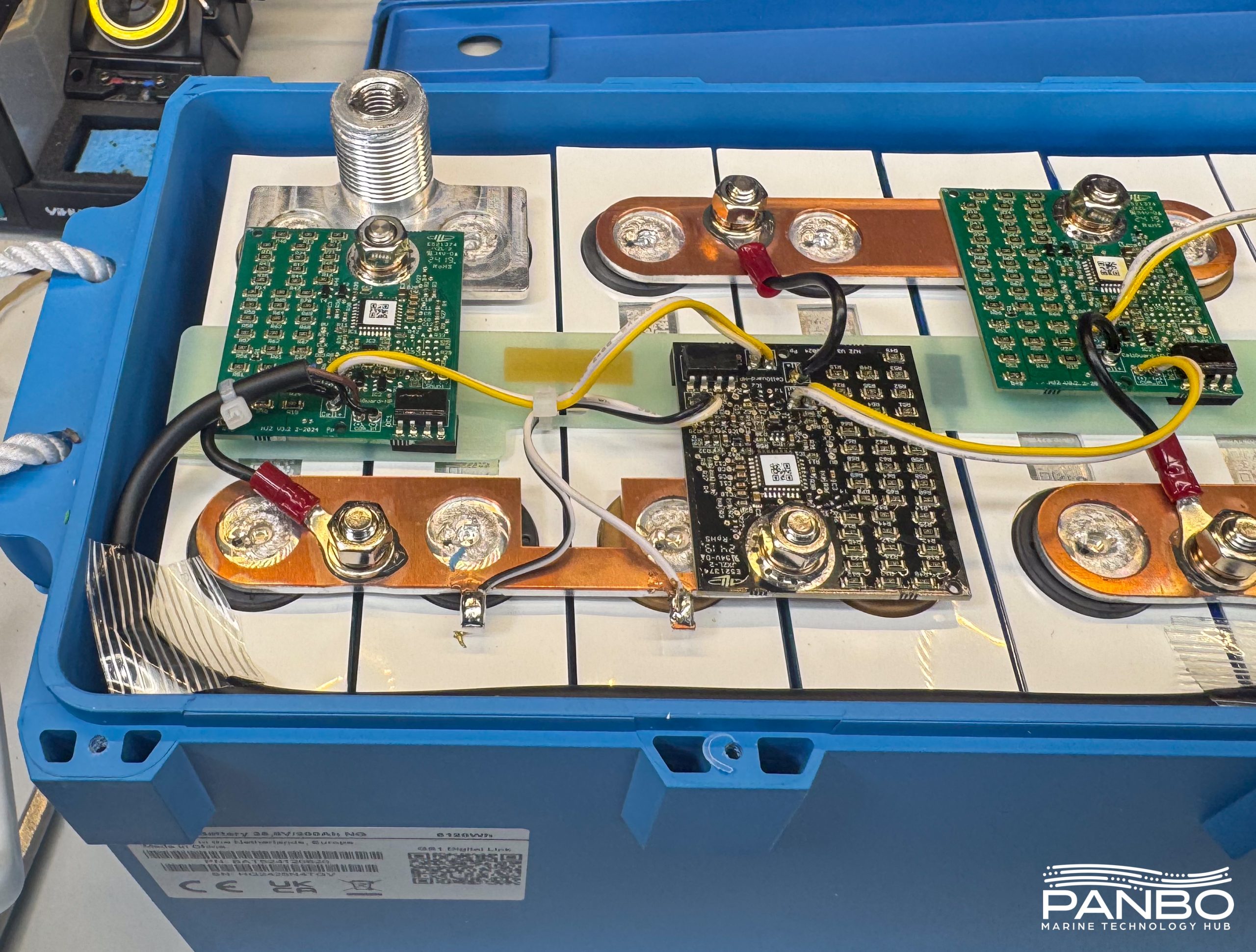
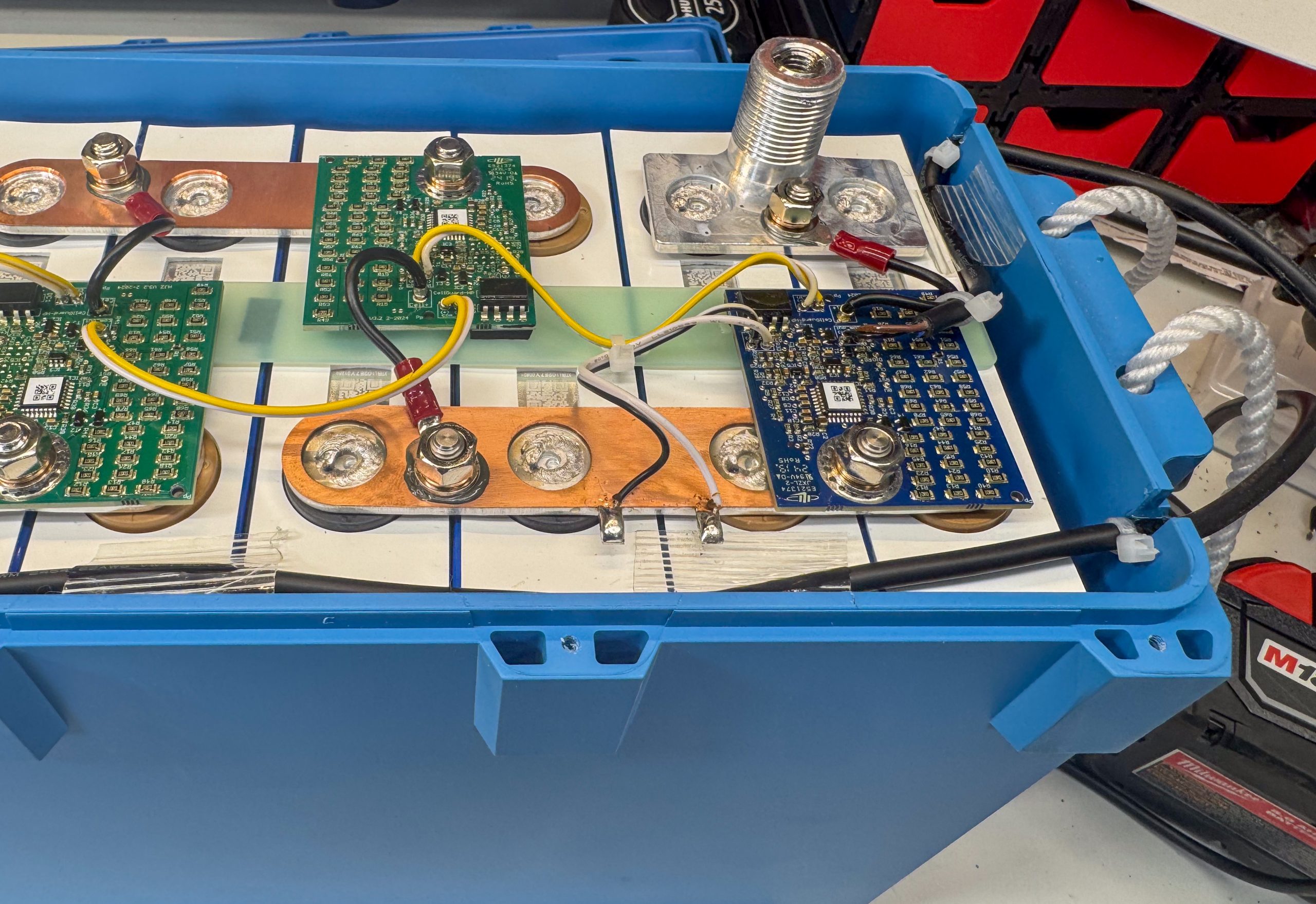
Interestingly, the outer most busbars both also serve as shunts. The cell management modules on these bus bars are different colors and have wires connected to their shunt terminals, unlike the other six modules. The black and white wires are shunt leads connecting between the bus bar, which must have a calibrated resistance, and the cell management module. The non-Lynx BMSs rely solely on these shunts for current measurements from the batteries.

Despite a good scan of the QR code, I have not been able to decode the cells’ QR codes to determine manufacturer or other information. I have run across this more and more frequently in recent reviews. I can’t draw any conclusions about what it means. It seems unlikely that Victron is cutting corners with cells but without the ability to look them up I simply don’t know.
Final thoughts
Victron’s NG batteries are a formidable energy solution. The introduction of parallel BMS functionality affords a lot of design flexibility to deliver large, robust, and efficient energy systems onboard even the largest of boats. But, as the table at the start of this article shows, those capabilities come at a cost. This is not a cheap system, although the costs do get more reasonable as you scale up the number of batteries behind a BMS. For those boats with simpler needs, there are many compelling options available at lower cost. But, for larger cruising boats operating beyond site of land, the design flexibility and robustness of Victron’s current solutions are tough to top.


Here is a thread in a Victron FB group where the manufacturer of the cells is conjectured: https://www.facebook.com/share/p/1Dt2azoitH/?mibextid=wwXIfr
I should have read the article before I posted on YT! Excellent review.
A few comments:
a crucial feature for anyone charging with an alternator is the 2-second pre-BMS disconnect signal provided through CAN to an alternator management system (Wakespeed or ARCO Zeus). This feature has been in the previous Lynx BMS, too. Without this, the dreaded load-dump risk is higher. (A blown fuse or other non-BMS related open circuit makes it a good idea to use an alternator protection device and a good alternator with avalanche diodes). I know of no other BMS with this feature (maybe Lithionics, MG or Mastervolt??)
No mention of the inconsistency in CVL values with the manual. The previous Lynx DVCC was consistent with 28.4v and 27v (absorption and float). This one seems to use 28.0v and 27.4v, respectively. How does this work with mixed Lynx BMS systems (classic with a retrofit NG)? Would this undercharge (sorta) the classic in absorption and hold the float for the NG lower? Would the classic SOC reset not occur because the voltage doesn’t get high enough to reset the system to 100%?
No mention of the Lynx mono-stable contactor being a suitable main battery switch for ABYC battery switch requirement. This is a major feature to me as I see lots of installs/designs without a main battery switch, at all. (The apparent logic is that there is an on/off switch in the battery—not compliant and not safe!)
I really appreciate your work on this (and other batteries). Perhaps an article on features and compatibility comparing some batteries so the buyer can be better informed and make a better value decision than $/kWh. Your table is awesome for the scale decision but many won’t comprehend the text explaining why you chose the configurations.
Cheers!
Jim,
I always post the videos before the article. It leaves a period where you have no way to read the article first. I think that period got you. No worries.
You are definitely correct that I didn’t cover everything about these batteries. As it was, this article ran over 3000 words and I feared making it longer. But, I may not have chosen too well about what didn’t make the cut. The pre-alarm is a great feature and Victron is certainly in rare company with it.
I don’t know for sure, but I think the difference in DVCC CVLs is due to the evolving view of the benefit of higher voltages. Essentially, bringing the cells higher has a negligible capacity difference. Lower votlages are kinder to the cells and extend life. My own testing (https://panbo.com/charging-lifepo4-whats-the-impact-of-lower-voltages/) shows very little difference between the voltages. 28.4v is 3.55 volts per cell compared to the 3.5 volts per cell at 28v. I don’t expect any difference in capacity.
I know there are multiple interpretations of E-13.6.7.1, but I don’t interpret it to mean the Lynx contactor is an acceptable battery switch. The text (below) clearly states the switch or other means of disconnection must be independent from the BMS. I don’t believe that a BMS controlled contactor qualifies. Interestingly, this basic topic came up in San Antonio at ABYC’s Standards Week last year with regards to Mastervolt’s use of RBSs. The determination there was consistent with the notion that a contactor controlled by the BMS doesn’t meet the independent requirement of 13.6.7.1.
“13.6.7.1 A battery switch or other means of disconnection independent from a BMS shall be installed for each battery or battery bank in addition to an output disconnect device.”
Thanks for the kind words. I’m doing the best I can. These batteries were a challenge because there is so much to cover.
-Ben S.
I was on the phone the entire meeting.
I didn’t know it was Mastervolt, Navico. I assumed (wrongly, I guess) that it was Victron. I agree the BMS control of the switch doesn’t qualify but there is a remote switch capability (physical ) to disconnect the power to the mono-stable contactor. Without power, (the switch provides this power, or not. ,The contactor opens, just like some RBSs (mono-stable, not the bi-stable versions). It consumes power to stay closed but it “fails” open (safe) when power is removed.
Being in the room, with a chance to side-bar and “bar-bar” later is a huge advantage. Glad you were there.
On the CVL voltages, 4.7 of the manual and 8.1 are slightly inconsistent on absorption and 27.4v float voltage isn’t anywhere I can find. It seems well above full charge resting voltage which is more consistent with keeping the batteries full and not overcharging. The sub-text of my question is how the classic and NG Lynx BMSs will control the charger output voltage with either the NG profile, the classic profile and whether the automatic selection in the GX will pick one or the other. (I’m happy to pay for shipping if you want me to test it 😉 )
Any thoughts on the Victron 2 hour absorption and 70% rebulk trigger versus, say, 15 mins per battery and 90% rebulk trigger?
No criticism intended on the article! I think it was awesome. I sure can’t write with the clarity and organization you have. I’ve tried…the adhd (or whatever I have which makes me pretty good at my day/night job) makes writing a report without extreme time /job pressure almost impossible.
Panbo is the best LFP power systems technical reviewing resource out there. Just about everyone else are just influencers.
Jim,
I think we have are reading 13.6.7.1. I don’t see the contactor itself as independent of the BMS. It’s built into the BMS and controlled by the BMS, so I see it as very much dependent on the BMS. My concern is that although you may be able to disconnect it separately, It is still part of the BMS and dependent on the BMS. My concern is, what if the BMS closes the contactor after I open it? That may sound far fetched, but a malfunctioning BMS may do unpredictable things. It is possible, maybe even likely, that the circuit design is such that a switch overrides the BMS’ ability to close the contactor. But, I don’t know that with enough certainty to stake the safety of a boat on it. My reading of 13.6.7.1 is that the disconnect means must be separate from the disconnect controlled by the BMS. In the case of FETs, that’s clean and obvios. In the case of contactors, it’s less obvious. It is even less obvious for Mastervolt where that contactor is external to the battery and BMS entirely.
I did hear from Victron that they’re aware of the inconsistency of float voltage as described in the manual and plan to clean that up in the near future. With regard to the subtext of a potential collision between the CVL commanded by classic and NG BMSs, I believe Victron’s table I screenshotted above is relevant here. That table suggests that for CVL, the lowest communicated value wins. So, I would expect the NG’s value to govern.
I think Victron’s 2 hour absorption is conservative, but without a little more exposure to their balancing algorithms, that’s just my uneducated opinion. I also feel like 70% is really low SOC to rebulk. Personally, I like values closer to 85% but also don’t see systems drop much below mid 90s for the most part.
Thanks for your conversation and contributions.
-Ben S.
Ben—yes, the 2022 E-13 would not permit the BMS contactor to act as the battery switch. The language for the 2025 E-13 should be out by August. It may (or may not) give you a chance to publish a short update on the Lynx BMS. I’m not talking about the software switching, which I agree would not meet the remote battery switch standard (C-7), but the REM pins and a remote battery switch.
Good to hear the clarification from Victron. I think irons a terrific feature for larger installs and upgrading legacy installs.
One feature of the Lynx BMS is the ability to configure the absorption time and re-absorb SOC (and repeated absorption time) trigger in VictronConnect to tailor to a particular use case. The user/installer can configure for how they use the system—so long as they get balanced cells by having enough time in absorption for the balancing to occur effectively before the clock runs out.
Cheers
Hmmm i’m not so impressed by the battery tear down. How are the cells held together? Is it just tape or a decent clamping construction?
The communication wires only have a zip tie on them as strain relief? This looks like cost cutting. A connector on the lid would seem nicer and makes it possible to make the case waterproof.
A remote BMS seems simpler, but how does it behave if the communication wiring gets damaged or loose? Is there a fail safe mechanism in case of a single fault situation? There is also quite a bit of unfused cabling in the system, not sure whats allowed in ABYC.
Contacters can be robust, but Mosfets allow disconnecting charge vs discharge current separately. So the BMS can cut off charging if a charging device does not listen to the communication (in e.g. overcharged or freezing situations), while keeping attached system alive. Same thing if the battery is discharged too deep, it can allow a charge but protect itself from discharging even further.
Juppe—can’t speak to the internals question but I do have some answers to what may be a misconception about how the system is intended to be configured and any waterproofing concern.
First, the NG battery is IP65–waterproof. It can’t handle immersion (ip67) but if the water is that deep, there might be other concerns. The previous version is IP22, probably because of the BTV (now called BMS cable probably because it’s not analog anymore) cabling or maybe because it just wasn’t tested. It appears very similar.
A loose BMS cable is improbable—the connector is robust( but a short or open circuit will fail-safe—BMS protections).
Not sure if you are looking at the demo system or something else when you question the unfused cabling. Comm wiring does not need to be fused. Current carrying wires, of course, do. The Power-INs and distributors have either class T (power in) or megafuses (distributor). Each is appropriate for its function. Anything powered by the BMS ‘s power supply that is not on the bus probably has a fuse (per the diagram) but I don’t see them in the pic—the only thing in the test rig that would need it is the cerbo and it may be powered/fused out of view.
The contactor is the safety switch, not the power (charge/discharge) control mechanism. Like Ben’s loose connector, I’ve only had one BMS disconnect in 3+ years—exact same cause, poorly torqued connector causing heat to the BMS. All loads are either off a smart battery protect (sbp) which is controlled by the Allow to Discharge (ATD) or through other coordination through the GX. Similarly, the Allow to Charge (ATC) functions are handled through either DVCC with the CANbus, VE.bus or ve.direct as well as an ATC signal for unmanaged chargers. Both of these ATC and ATD systems work well, just the functions aren’t BMS mosfet controlled. They are controlled by the BMS with more discretization than a a 2 channel charge/discharge mosfet or a single contactor system can employ.
Take a look at the diagrams and manuals on the Victron site. The engineering is impressive. Several functionalities may be distributed differently but the system is much more extensive than an internal serial BMS with or without communications.
(Yes , I’m a fan, but I think it has been earned.)
Jim
I’m not a fan of any system or brand, they each have their pros and cons depending on the application.
The IP65 claim is questionable. It is at most IP33, as it clearly has openings on the side.
You are probably right about the fail-safe in case of a loose connector, it could just open the contactor. I wouldn’t say a connector coming loose is improbable, while doing a system FMEA it is usually considered a regular fail. But it could have a safe outcome because of the fail-safe feature, as long as there are no critical systems being powered.
I’m not familiar with all the comm systems Victron uses, I’m sure there must be proper engineering behind it all.
I was just a bit shocked seeing the opening in the battery side, the fixed comm wires and the zip-tie as strain relief. On the schematics there are connectors drawn in that location, its seems like a last minute cost down.
Please don’t misconstrue my fan status as an inability to be critical of any system (or sports team (lifelong Redskins fan)). I install and use other companies components (including LFP batteries ) where appropriate. For example, I use ip67 rated LFP starter/windlass batteries and have installed them 8-12” above my generally dry (but with condensate drains and keel stepped mast, so not dry, dry) bilge… technically, an ip54 battery would meet the requirements of this installed location, but the higher rated protection does make me feel better about using this location which otherwise is simply a (damp) wine cellar
I would hope an FMEA would assess each identified improbable event and its likely outcomes. The type of connector and other requirements for the install (eg, M8 and secured battery) all play into the acceptable risk, but it’s always (engineering!) judgement until the accident investigation shows the judgement was not correct.
I see, now, what you are seeing which makes you question the IP rating. I think the cable glands are missing in the picture. The EU world is pretty strict on manufacturers claims to a standard and the testing needed to make the claim. But, it’s worth questioning if the holes seen are artifacts of the teardown or not. Good catch.
There’s pretty good documentation scattered across the Victron site on the comms. They are not as deep an interoperability document as one might want, but it’s more than expected for the public/consumer level. It’s way more than what you would find at any LFP reseller/manufaturer website that I’ve seen. (Buyer beware of what “Victon Comms” means to the marketing department.)
Cheers , and thanks (you made my day with “FMEA”. )
Great piece of work Ben, very informative and a huge subject due to the complexity/scope of these Victron systems -well done and thanks for sharing your efforts.
One observation re LFP batteries however is they are inherently very safe, but for marine i.e. saltwater applications most people don’t seem to consider the dangers of flooding/immersion, and most boat installations feature batteries placed low in the vessel. To that end LFP batteries with internal mosfet based BMS’s offer what I consider to be a significant advantage, during localised flooding they are extremely unlikely to create a high risk short circuit. I’ve dismantled a customer’s returned IP65 battery that had been immersed. It had simply stopped working due to the BMS shutoff and otherwise appeared fine externally. Internally it was quite damp although didn’t have pooled water, and in fact the BMS started operation again after it had dried out.
So batteries requiring external contactors have greater risk both due to flooding, plus also wrt maintenance . They are equivalent to having bare cells with exposed connections.
Are the Lithium Smart NG batteries and the Smart BMS NG’s ignition protected? Can these components be located in the engine room of a gasoline powered recreational vessel? Same question relative to Victron Inverter/Chargers?
Thanks Ben for this great and, for us, very timely summary.
I will need to study it in much more detail, but a dual 24V/300Ah dual BMS system looks what we’ll shoot for.
“Rather than connecting using a distributor connected directly to one BMS, the distributor could be remote to both BMS. Then, equal length wires can be employed to connect both BMSs to the distribtor.”
That was my first thought when I saw the setup on the Victron diagram.